Positive-Fit Freewheel Mechanism That Can Be Electromechanically Actuated, Electromechanical Brake With A Freewheel Mechanism Of This Type For A Motor Vehicle and Method For Adjusting The Play In A Brake Of This Type

a freewheel mechanism and positive-fit technology, applied in the direction of mechanical actuated clutches, mechanical interlocking clutches, mechanical apparatus, etc., can solve the problems of oscillation, vibration, impact,

Inactive Publication Date: 2009-08-06
ROBERT BOSCH GMBH
View PDF21 Cites 10 Cited by
  • Summary
  • Abstract
  • Description
  • Claims
  • Application Information

AI Technical Summary

Benefits of technology

[0008]In comparison to a frictionally engaging, so-called clamping freewheel mechanism, the form-locking embodiment of the freewheel mechanism according to the invention gives it the advantage that it does not inadvertently disengage from the switched-on, locked state. In a clamping freewheel mechanism, it is conceivable for an inadvertent release to occur due to sliding movements between the clamping element(s) that constitute(s) the locking elements and a component that is to be prevented from rotating in the locking direction. This is particularly if, in order to adjust a clearance of a brake while driving, the freewheel mechanism is switched on and is thus subjected to oscillations, vibrations, and impacts. In addition, when there are different thermal expansions, a cooling can lead to a sliding of the clamping elements of a frictionally engaging freewheel mechanism, which then release the freewheel mechanism.
[0009]Another advantage of the freewheel mechanism according to the invention is its compact design in the form of an electric motor, but with a limited pivoting angle of the armature. An additional advantage is the possibility of embodying it in a comparatively simple fashion from a structural standpoint, with the armature equipped with the locking element being the sole moving component. In this case, a rotating or pivoting support must be viewed as less susceptible to malfunction than a sliding guidance, for example of the bar of the known freewheel mechanism described above as the prior art.

Problems solved by technology

This is particularly if, in order to adjust a clearance of a brake while driving, the freewheel mechanism is switched on and is thus subjected to oscillations, vibrations, and impacts.

Method used


Image

  • Positive-Fit Freewheel Mechanism That Can Be Electromechanically Actuated, Electromechanical Brake With A Freewheel Mechanism Of This Type For A Motor Vehicle and Method For Adjusting The Play In A Brake Of This Type
  • Positive-Fit Freewheel Mechanism That Can Be Electromechanically Actuated, Electromechanical Brake With A Freewheel Mechanism Of This Type For A Motor Vehicle and Method For Adjusting The Play In A Brake Of This Type
  • Positive-Fit Freewheel Mechanism That Can Be Electromechanically Actuated, Electromechanical Brake With A Freewheel Mechanism Of This Type For A Motor Vehicle and Method For Adjusting The Play In A Brake Of This Type

Examples


Embodiment Construction

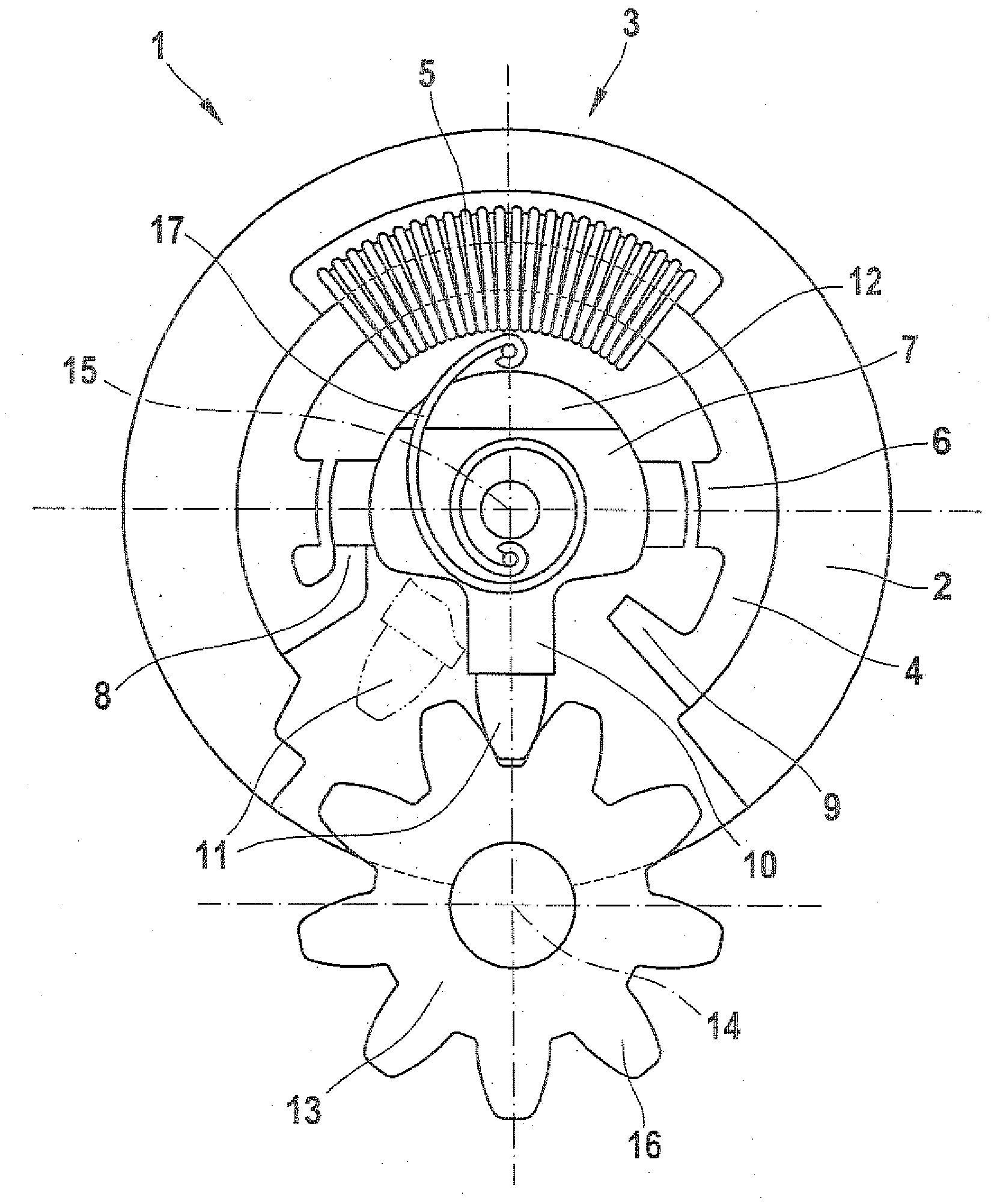
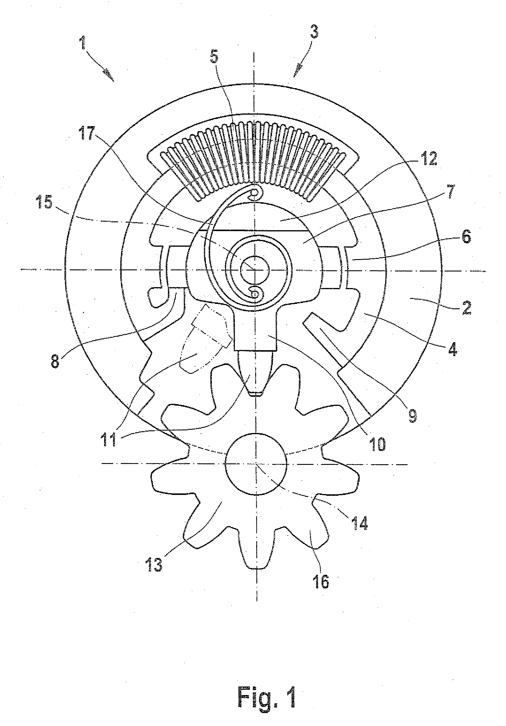
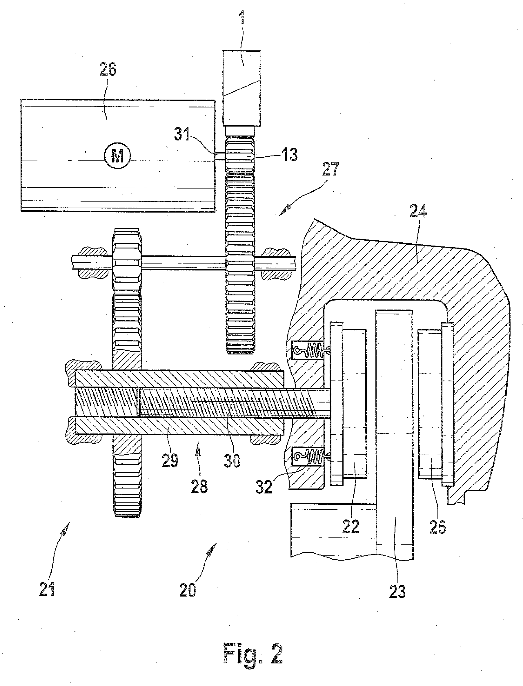
[0018]The freewheel mechanism 1 according to the invention shown in FIG. 1 is electromechanically switchable and functions in a form-locking fashion. Its design is comparable to that of an electric motor. The freewheel mechanism 1 has a hollow, cylindrical housing 2 equipped with an electromagnet 3. The electromagnet 3 has a likewise hollow, cylindrical yoke 4, also referred to as a stator, on which a coil 5 is situated. The yoke 4 is inserted, for example press-fitted, into the housing 2. The yoke 4 has two pole shoes 6 that protrude radially inward and are situated opposite from each other.

[0019]An armature 7 is pivotably supported coaxially in the housing 2 and its rotation angle is limited by two stops 8, 9. The stops 8, 9 protrude inward from the yoke 4. A locking element 10 with a tooth 11 protrudes radially from the armature 7. The locking element 10 is integrally joined to the armature 7. The armature 7 has a counterweight 12 opposite from the locking element 10; the armatur...


PUM


Abstract

The invention relates to an electromechanically switchable form-locking freewheel mechanism for preventing an electromechanical brake from releasing. According to the invention, the freewheel mechanism is embodied in the form of an electric motor in which a pivot angle of the armature is limited, the armature is counterbalanced and has a locking element that cooperates with a gear. The invention permits a compactly designed freewheel mechanism that can be integrated into an electromechanical actuating unit of the electromechanical brake. The counterbalancing of the armature equipped with the locking element prevents external accelerations of the freewheel mechanism of the kind that can occur during driving operation of a motor vehicle from exerting a moment on the armature that could switch off the freewheel mechanism. A method for adjusting the clearance of an electromechanical brake is also provided.

Description

PRIOR ART[0001]The invention relates to an electromechanically switchable form-locking freewheel mechanism with the defining characteristics of claim 1. In particular, the freewheel mechanism is provided for use in an electromechanical brake for a motor vehicle in order to modify the brake into an auxiliary brake (parking brake). The invention also relates to an electromechanical brake of this kind for a motor vehicle, equipped with a freewheel mechanism as recited in the preamble to claim 8 and to a method for adjusting the clearance in the brake as recited in the preamble to claim 10.[0002]Freewheel mechanisms are intrinsically known; they are also referred to as one-way clutches. A freewheel mechanism prevents a component, for example a shaft or a cage / housing, from rotating in a locking direction and permits the component to rotate in the opposite rotation direction, which is referred to as the freewheeling direction. The prevention of rotation in the locking direction can also ...

Claims


Application Information

Patent Timeline
Patent Type & Authority Applications(United States)
IPC IPC(8): F16D41/08F16D67/06
CPCF16D65/14F16D2121/24F16D2129/08F16D2125/48F16D2127/06F16D2125/40
Inventor CAO, CHI-THUANHOFMANN, DIRKVOLLERT, HERBERTNAGEL, WILLIFOITZIK, BERTRAMGOETZELMANN, BERND
Owner ROBERT BOSCH GMBH
Why Eureka
Try Eureka