Eureka AIR delivers breakthrough ideas for toughest innovation challenges, trusted by R&D personnel around the world.

Crushing Apparatus for Demolition or Similar Works

a technology of crushing apparatus and demolition, applied in the field of crushing apparatus for demolition or similar works, can solve the problems of requiring a considerable amount of time and the inability to operate normally, and achieve the effect of convenient breaking

Inactive Publication Date: 2009-08-06
CORIMAG
View PDF7 Cites 6 Cited by
  • Summary
  • Abstract
  • Description
  • Claims
  • Application Information

AI Technical Summary

Benefits of technology

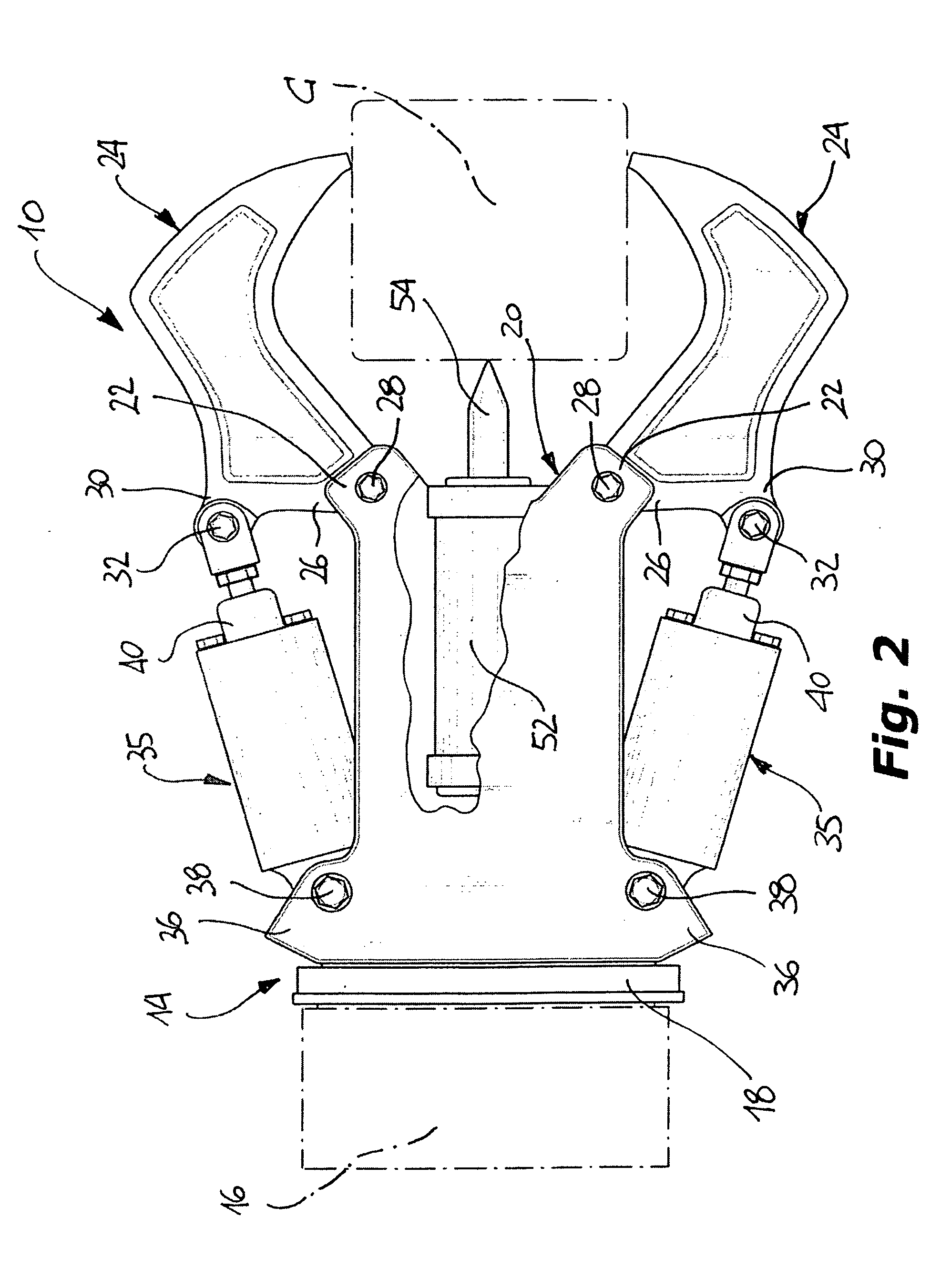
[0006]By virtue of the fact that the apparatus according to the invention is provided with percussion means associated with the main body, which are intended to apply a percussion force to the material to be demolished, together with the compressive action performed by the jaws, the demolition work turns out to be extremely effective and allows the time of demolition to be considerably reduced. Moreover, the demolition apparatus of the invention has a simple structure, and can be manufactured at a low cost starting from componentry which is mostly available on the market.
[0008]In this manner, the jaws simultaneously carry out a concentrated action, both of compression and percussion, on a member to be crushed, and therefore perform a very effective breaking up action.
[0010]In this manner, the action of percussion of the demolishing unit is carried out when a member to be demolished is already firmly grasped by the jaws, which allows, on the one hand, that the action of percussion is applied to a preselected zone of the member and, on the other hand, that the breaking up action by compression of the jaws is made more effective, by virtue of the fact that percussion of the demolishing unit allows to weaken the member to be broken up, which makes easier breaking up thereof by compression.

Problems solved by technology

However, this manner of acting has the drawback of requiring a considerable time, since the breaking up action carried out by compression applied through the jaws is progressive and, after all, rather slow.

Method used


Image

  • Crushing Apparatus for Demolition or Similar Works
  • Crushing Apparatus for Demolition or Similar Works
  • Crushing Apparatus for Demolition or Similar Works

Examples


Embodiment Construction

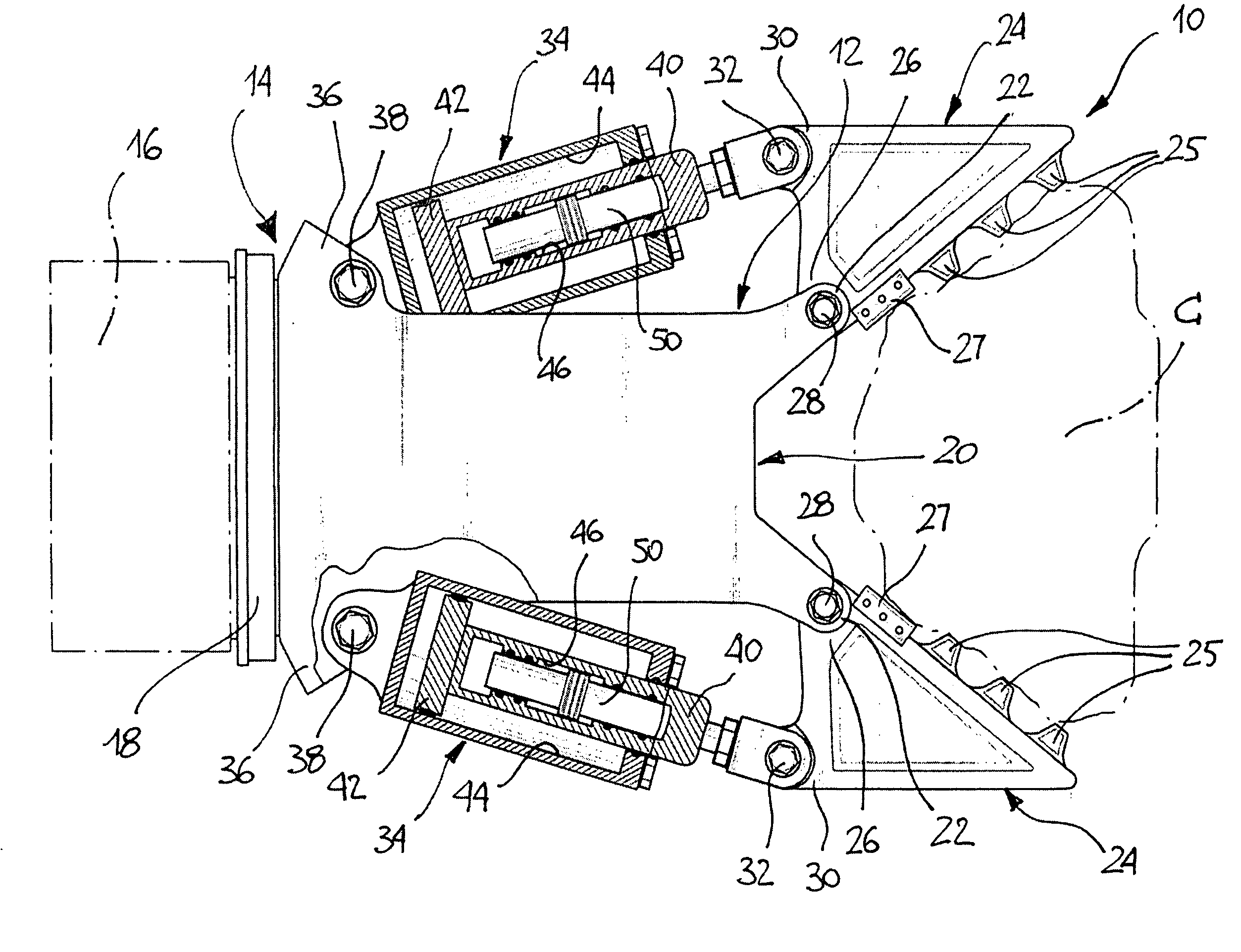
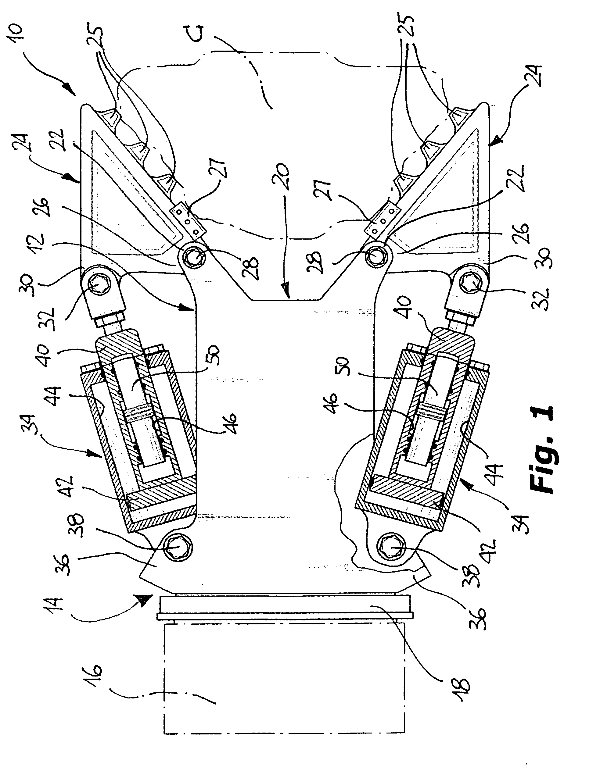
[0014]With initial reference to FIG. 1, a crushing apparatus for demolition or similar works, made according to a first embodiment of the invention, is indicated 10 in its whole. The apparatus 10 comprises an elongated main body 12 having a first portion 14 intended to be removably connected to the free end of a handling arm, schematically indicated 16, of an operational machine, with the aim of carrying the apparatus 10 close to a member C, typically of concrete or reinforced concrete, to be demolished.

[0015]The body 12 is usually rotatably mounted on a fifth wheel support member 18, in order to allow rotation thereof about its general axis with respect to the arm 16.

[0016]The second end 20, or distal end, of the body 12, opposite to the first end 14, is conveniently fork shaped being defined by a pair of appendages 22 which are preferably symmetrical with respect to the general axis of the body 12, a respective jaw 24, swingably mounted, being associated with each appendage.

[0017]...


PUM


Abstract

Crushing apparatus for demolition or similar works A crushing apparatus for demolition works comprises a main body having a connecting portion intended to be connected to the end of a handling arm, and at least a swingable jaw articulated to the main body at a distal portion with respect to the connecting portion, which is adapted to allow, during a demolition work, that a member to be demolished is grasped. Actuator devices are interposed between each swingable jaw and the main body, which are intended to control the movement of the respective jaw. The apparatus comprises percussion devices adapted to carry out an action of percussion on a member to be demolished, while it is grasped by said at least one jaw.

Description

BACKGROUND OF THE INVENTION[0001]The present invention refers in general to apparatuses to be used for performing demolition works, for example for breaking up members of a building structure, such as concrete beams or pillars, or in quarries during works carried out in order to crush blocks, stones or similar materials.[0002]More particularly, the invention relates to a crushing apparatus for demolition or similar works, of the type defined in the preamble of appended claim 1.[0003]Apparatuses of the type known mentioned above are commonly used for breaking up structural members of buildings during demolition works, and comprise a main body intended to be removably associated to the free end of an articulated handling arm of an operational machine such as an excavator. A pair of jaws, which may be provided with teeth and / or shear blades, and at least one of which is movable, is associated to the main body. The movement of the movable jaws is controlled by actuators, usually consist...

Claims


Application Information

Patent Timeline
IPC IPC(8): B02C19/00
CPCE02F3/965E04G23/08E02F5/305E04G23/082
Inventor ANDRINA, GIOVANNI
Owner CORIMAG
Why Eureka
Eureka Blog
Learn More