Protective circuit

a protection circuit and circuit technology, applied in relays, pv power plants, transportation and packaging, etc., can solve the problems of affecting the power output of the module, the output voltage of individual solar cells is typically too small to be able to operate electrical devices, and the parallel connection of solar cells has not prevailed, so as to minimize the risk and small space

Active Publication Date: 2009-08-06
FRAUNHOFER GESELLSCHAFT ZUR FOERDERUNG DER ANGEWANDTEN FORSCHUNG EV
View PDF6 Cites 151 Cited by
  • Summary
  • Abstract
  • Description
  • Claims
  • Application Information

AI Technical Summary

Benefits of technology

[0014]Proceeding from the initially described protective circuit, the above described object is achieved by the protective circuit having a controlled electronic circuit arrangement as a protective means. Therefore in accordance with the invention, it is provided that, to prevent the above described problem which is associated with partially shaded solar cells, the protective means is a controlled electronic circuit arrangement so that the use of bypass diodes can be reduced or entirely avoided. By replacing bypass diodes with a controlled electronic circuit arrangement which is functionally essentially identical to the bypass diodes, the heating of the circuit arrangement can be reduced, as described below.
[0017]According to another preferred embodiment, it is alternatively provided that the protective means is a controlled electronic circuit which, for at least one string of solar cells, has at least one transistor and at least one DC / DC converter which is switched parallel to the latter and which is connected to the trigger circuit via an energy storage device. In this execution, it is especially advantageous that the protective means has economical MOSFETs with a small space requirement because from the low forward voltage of the parasitic diode of the MOSFET, the voltage necessary to trigger it is produced using a voltage converter.
[0018]Furthermore, it is especially advantageous if voltage conversion takes place by integration of a protective means into at least two strings of solar cells of a solar cell module. On the one hand, it is possible such that the protective means is adequately supplied in alternation from the voltage present over one MOSFET, because there are several MOSFETs. On the other hand, when all the solar cells belonging to a string are shaded, a sufficient voltage can be obtained from the total of the forward voltages of the parasitic diodes of the MOSFETS in order to use this voltage for conversion and triggering of the MOSFETs. Moreover, it is advantageous that the maximum voltage occurring in the backward direction per protective means is limited to the forward voltage of a silicon diode; this minimizes the risk of complete failure of supply when there is insufficient illumination of the solar cells that are remaining in operation, for example, due to diffuse light.

Problems solved by technology

In this connection, the solar cells connected in parallel should have essentially the same physical properties so that, in practice, parallel connection of solar cells has not prevailed, especially also since the individual solar cells can already deliver a current of a few amperes and the output voltage of individual solar cells is typically too small to be able to operate electrical devices, such as household appliances.
However, a problem can arise when a solar cell module is partially shaded in operation, so that one solar cell or a majority of solar cells of the solar cell module acquires less solar radiation or none at all, thereby affecting power output from the module.
In contrast to shading of the solar cell module uniformly over the entire area, which leads only to a power reduction overall, the following problem arises with partial shading: A common current flows through the series-connected solar cells of the solar cell module, each individual solar cell with its respective voltage contributing to the overall voltage of the solar cell module.
This means that the entire solar cell module can no longer deliver current so that the entire operation of the solar cell module is adversely affected.
If the voltage which is present on the shaded solar cell is greater than its reverse voltage, a breakdown, and thus, permanent damage will occur in the solar cell.
Even if the solar cell should not be damaged by a breakdown, in a shaded solar cell, a large power loss is converted so that the shaded solar cell heats up.
This heating can also lead to damaging of the shaded solar cell and the solar cells adjacent to it.
This results in that a shaded solar cell no longer contributes to the total solar cell voltage, but the current flow is nevertheless maintained.
However, this is associated with the problem that the protective circuits used for electrical connection of solar cells of a solar cell module are greatly heated by the power converted into the bypass diodes; this is disadvantageous in various respects.

Method used


Image

  • Protective circuit
  • Protective circuit
  • Protective circuit

Examples


Embodiment Construction

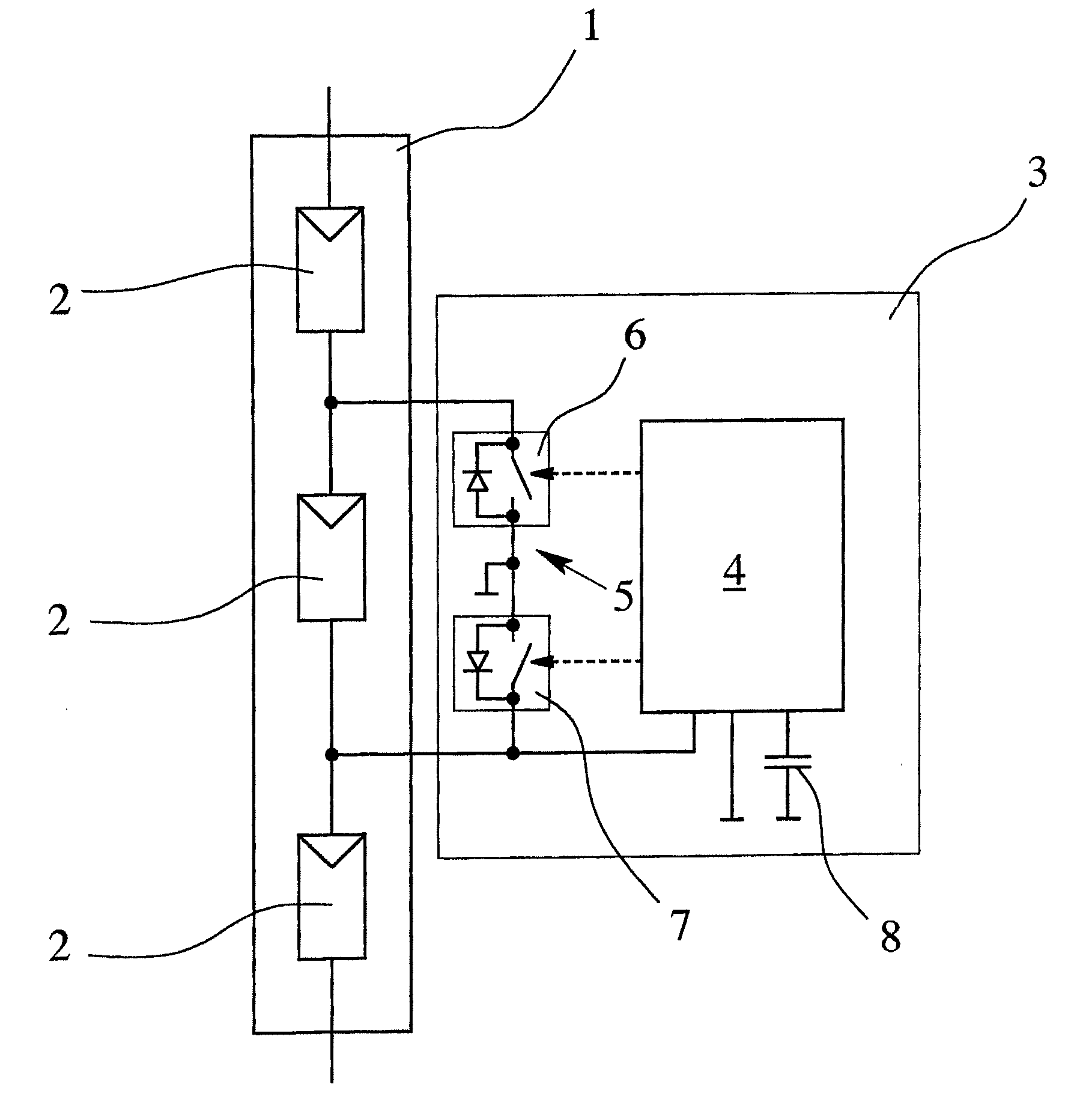
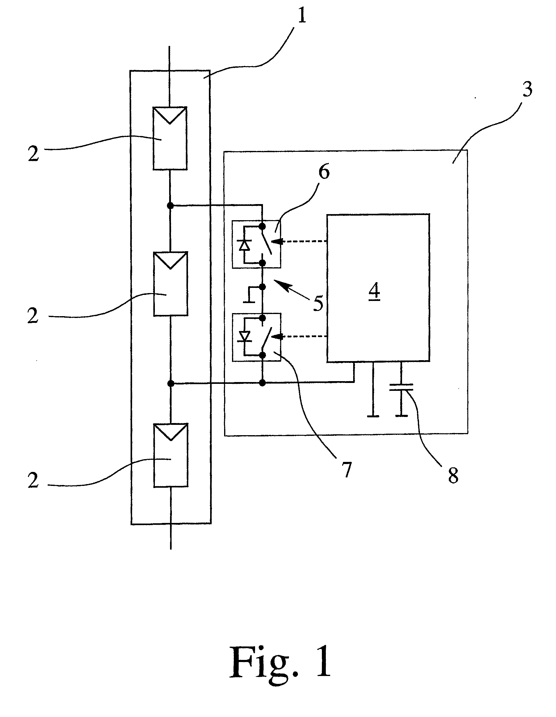
[0027]FIG. 1 shows a solar cell module 1 which has a plurality of series-connected solar cell strings 2 which, for their part, are comprised of several, likewise, series-connected solar cells which are not shown individually. The provision of three strings 2 for the solar cell module 1 is used purely an example. Likewise, safeguarding via a protective circuit according to one preferred embodiment of the invention is shown, by way of example, for only one of the strings 2. There can, of course, corresponding safeguarding can be provided for each string 2.

[0028]As already mentioned, the objective is to devise a protective circuit which ensures that, in the case of shading of the string which is being safeguarded, current bypass for this shaded string is achieved, so that the solar cell module 1, on the one hand, continues to be ready for operation, i.e., delivers a current, and on the other hand, damage of the shaded string 2 is prevented. For this purpose, the protective circuit has ...


PUM


Abstract

A protective circuit for electrical connection to solar cells of a solar cell module is provided with a protective circuit that has a controlled electronic circuit arrangement. In this way, only minimal heating of the protective circuit for electrical connection of solar cells of a solar cell module occurs in operation. The controlled electronic circuit arrangement can have a trigger circuit and a switching arrangement which can be triggered by the trigger circuit, the switching arrangement being connected parallel to at least one solar cell, and in the case of shading of the solar cells, is at least temporarily activated by the trigger circuit so that a current bypass for the shaded solar cell is achieved.

Description

BACKGROUND OF THE INVENTION[0001]1. Field of the Invention[0002]The invention relates to a protective circuit for electrical connection to solar cells of a solar cell module, with a protective means which, in the case of a shaded solar cell, acts as a current bypass for the shaded solar cell.[0003]2. Description of Related Art[0004]Protective circuits for electrical connection to solar cells of a solar cell module are well known from practice in diverse versions. These circuits are also partially called terminal circuits for solar cells.[0005]Generally, several solar cells are interconnected into solar cell modules. In this regard, there is either the possibility of series connection or the possibility of parallel connection of the solar cells in the solar cell module. By parallel connection of the solar cells, the individual currents of the solar cells are added to one another to form a total current. In this connection, the solar cells connected in parallel should have essentially...

Claims


Application Information

Patent Timeline
Patent Type & Authority Applications(United States)
IPC IPC(8): H02H3/00
CPCH01L31/02021H02S50/00Y02E10/50
Inventor QUARDT, DIRKGROSCH, VOLKERGROSSEN, THOMASMUNDINGER, HARALD
Owner FRAUNHOFER GESELLSCHAFT ZUR FOERDERUNG DER ANGEWANDTEN FORSCHUNG EV
Why Eureka
Try Eureka