

Perceptually linear LED brightness control
a technology of led brightness control and perception, applied in the direction of electric variable regulation, process and machine control, instruments, etc., can solve the problems of reducing the efficiency of lighting, and requiring complex computation
- Summary
- Abstract
- Description
- Claims
- Application Information
AI Technical Summary
Benefits of technology
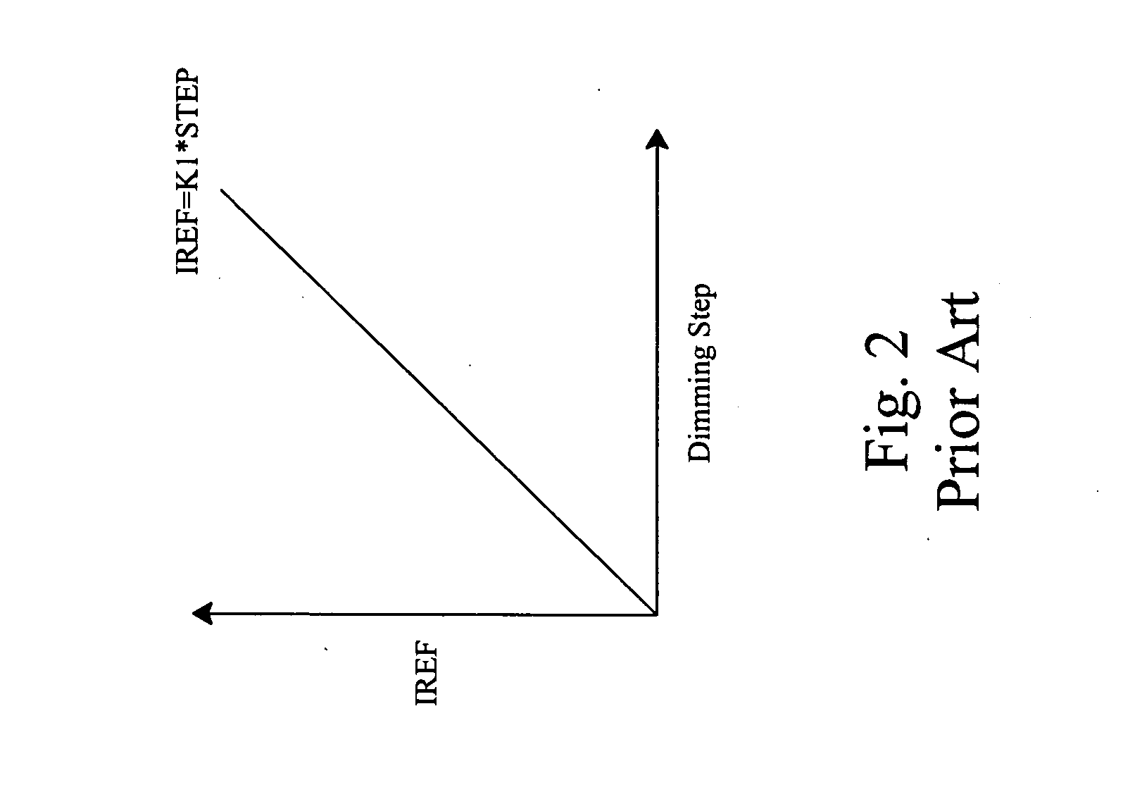
Problems solved by technology
Method used
Image

Examples
first embodiment
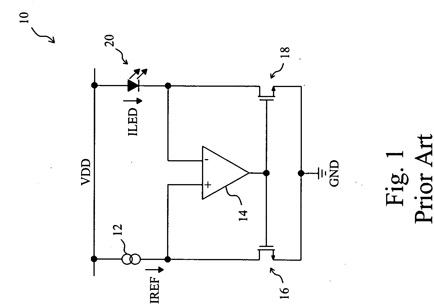
[0032]FIG. 7 shows a first embodiment according to the present invention. In a current regulator 40, a first current source 42 provides a reference current IREF=K1×((L+16) / 116)3, where K1 is a constant and L represents lightness, a brightness controller 44 determines the value of L, which also represents the dimming step, and a second current source 46 generates a DC drive current ILED for a white LED 48 according to the reference current IREF. In this embodiment, the second current source 46 includes an operational amplifier 4602 and two transistors 4604 and 4606 configured to be a low drop-out (LDO) current source as that of FIG. 1. The transistor 4604 is connected between the first current source 42 and a ground terminal GND, the transistor 4606 is connected between the white LED 48 and the ground terminal GND, and the operational amplifier 4602 has a non-inverting input and an inverting input connected to the drains of the transistors 4604 and 4606 respectively, and an output co...
second embodiment
[0035]FIG. 11 is a circuit diagram of a second embodiment according to the present invention. In a current regulator 60, a first current source 62 provides a reference current IREF=K1×((L+16) / 116)3 characterized by the curve 54 in FIG. 8, a brightness controller 64 determines the value of the lightness L, which also represents the dimming step in this embodiment, and a second current source 46 generates a drive current ILED for a white LED 48 according to the reference current IREF, which has the relationship with the dimming step as shown by the curve of FIG. 9. In the first current source 62, a voltage-current converter 6202 converts a reference voltage VREF into a dimming current I1, a pulse width modulation (PWM) signal generator 6204 generates a control signal PWM according to the output L of the brightness controller 64 to switch a switch S1 connected between the voltage-current converter 6202 and a ground terminal GND to switch the dimming current I1, thereby controlling the ...
third embodiment
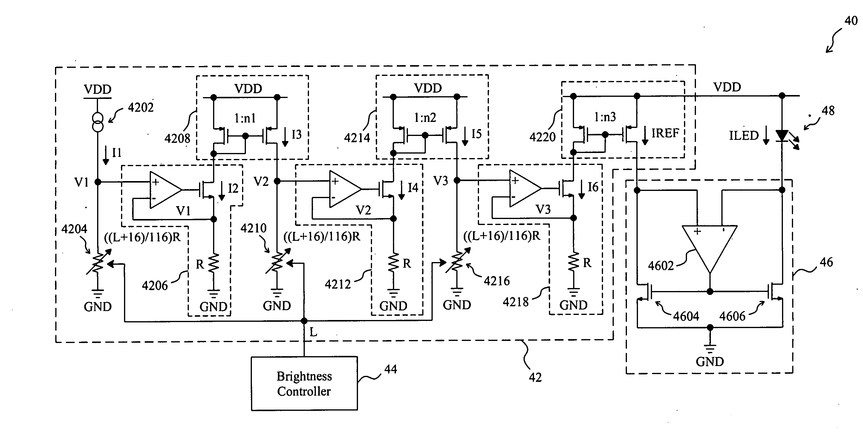
[0036]FIG. 13 is a circuit diagram of a third embodiment according to the present invention. In a current regulator 66, a first current source 68 provides a reference current IREF=K1×((L+16) / 116)3 characterized by the curve 54 in FIG. 8, a brightness controller 69 determines the value of the lightness L, which also represents the, dimming step in this embodiment, and a second current source 46 generates a drive current ILED for a white LED 48 according to the reference current IREF. In the first current source 6&, two variable resistors 6804 and 6810 have the same resistance ((L+16) / 116)×R, a current source 6802 provides a source current I1 to the first variable resistor 6804 to generate a first dimming voltage V1=((L+16) / 116)×R×I1 thereacross, a first voltage-current converter 6806 converts the first dimming voltage V1 into a first dimming current I2=((L+16) / 116)×I1, a first current mirror 6808 mirrors the first dimming current 12 to generate a first mirror current I3=((L+16) / 116)...
PUM
 Abstract
Description
Claims
Application Information