Apparatus for extracting operating object and apparatus for projecting operating hand

Inactive Publication Date: 2009-08-06
DENSO CORP
View PDF7 Cites 30 Cited by
  • Summary
  • Abstract
  • Description
  • Claims
  • Application Information

AI Technical Summary

Benefits of technology

[0013]By displaying the marker at the tip of the marker finger, the user can recognize which part of the marker finger is touching on the touch panel in advance. Further, the marker finger marked by the

Problems solved by technology

The drawback of the size reduction of the operation panel of the apparatus is that a ratio of the operator's finger size against the size of the operation panel increases.
As a result, the finger images displayed on the display panel of the vehicular device such as a display panel of a navigation apparatus occupies an increased portion of a display area of the display panel, thereby deteriorating, for the operator, the operability and/or intelligibility of the operation performed on the operation panel as shown in FIG. 20.
However, in the disclosure of JP-A-2008-158675, the finger shape, in particular the outline of the finger shape, is lost from the resulti

Method used


Image

  • Apparatus for extracting operating object and apparatus for projecting operating hand
  • Apparatus for extracting operating object and apparatus for projecting operating hand
  • Apparatus for extracting operating object and apparatus for projecting operating hand

Examples


Example

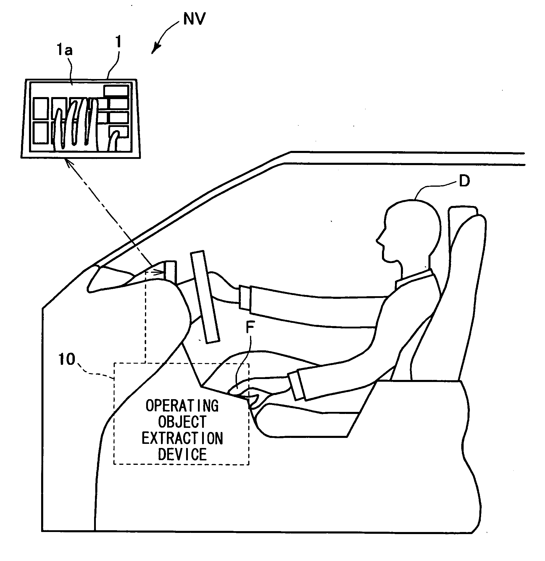
[0052]The first embodiment of the present invention is explained with reference to the drawings in the following. FIG. 1 is a schematic illustration of a car navigation apparatus NV including an in-vehicle operating object extraction apparatus regarding the present invention. The car navigation apparatus NV includes a display unit 1, and an operating object extraction apparatus 10.

[0053]The display unit 1 (a display part) has a liquid crystal panel 1a, and it is disposed in a front part of the vehicle compartment to be viewable by a vehicle driver D. The display unit 1 displays a vehicle symbol for navigation on a map, and various information such as traffic information is provided for the vehicle driver D from the display unit 1.

[0054]The operating object extraction apparatus 10 has a function to remotely control the car navigation apparatus NV, and a finger-tip image of the vehicle driver D (an operator) in the liquid crystal panel 1a of the display unit 1. The operating object ex...

Example

Second Embodiment

[0069]In the first embodiment, the capture control unit 16 is configured to carry out the photography control program of FIG. 4, and the image control unit 17 is configured to carry out the image processing program of FIG. 5. However, the capture control unit 16 may be configured to carry out a photography control program of FIG. 14, and the image control unit 17 may be configured to carry out an image processing program of FIG. 15. Other configurations of the present embodiment are same as the ones in the first embodiment.

[0070]In the present embodiment, the finger-tip image at a time when both of the lights 12a, 12b are turned off is acquired in addition to the finger-tip images acquired at times when each of the lights 12a, 12b is turned on. A photography control program of FIG. 14 is explained first.

[0071]As for the photography control program, the process is started in step S30.

[0072]When a palm or a wrist of the vehicle driver D is detected by the hand detecto...

Example

Third Embodiment

[0078]The photography control program in FIG. 14 executed by the capture control unit 16 may be replaced with the program in FIG. 17 for acquiring the binarized left difference image and the binarized right difference image by the camera 11 respectively at two steps as shown in FIG. 18.

[0079]The photography control program of FIG. 17 is different from the photography control program of FIG. 14 at the point that processing of step S131 is inserted between step S34 (light 12a turn off control) and step 35 (light 12b turn on control). In other words, while the both lights extinguished image is acquired by the processing only in step S38 in the program of FIG. 14, the programs of FIG. 17 acquires the both lights extinguished image by the processing in step S131 at a period between the turning off of the light 12a and the turning on of the light 12b.

[0080]According to the present embodiment, the number of images (i.e., binarized left difference images and binarized right...


PUM


Abstract

An operating object extraction apparatus uses a camera, a light, a memory, an operation panel, a hand detector, a capture controller, and an image controller for displaying an operating object such as an operating finger of an operator's hand, when the operating object extraction apparatus is used in combination with a navigation apparatus in a vehicle for remotely controlling the navigation apparatus by an input from the operation panel that that is disposed separately from the navigation apparatus. The operating finger of the operator's hand is displayed as a finger image on the display unit under control of the capture controller and the image controller in a manner that a finger tip of the operating finger occupies only a small portion relative to the size of the operation panel.

Description

CROSS REFERENCE TO RELATED APPLICATION[0001]The present application is based on and claims the benefit of priority of Japanese Patent Applications No. 2008-25874, filed on Feb. 6, 2008, and No. 2008-70864, filed on Mar. 19, 2008, the disclosure of which are incorporated herein by reference.FIELD OF THE INVENTION[0002]The present disclosure generally relates to an operating object extraction apparatus and an operating hand projection apparatus for use in a vehicle.BACKGROUND INFORMATION[0003]Conventionally, operating object extraction apparatuses are disclosed, for example, in a Japanese patent document JP-A-2007-272596, in which the apparatus has an operation panel disposed separately from a display unit of a vehicular device and displays, as finger images of an operating hand on the display unit in a superposing manner, operating fingers on the operation panel captured by a camera for the purpose of enabling a remote control of the vehicular device. The operating object extraction ...

Claims


Application Information

Patent Timeline
IPC IPC(8): B60Q1/00G06K9/00G06F3/041G06V10/141
CPCG06K9/2027G06F3/0425G06V10/141
Inventor AICHI, ISAOOKI, TETSUYA
Owner DENSO CORP
Why Eureka
Try Eureka