Panoramic Imaging Device

a technology of panoramic imaging and camera, which is applied in the field of panoramic imaging devices, can solve the problems of complex program, barrel distortion at the periphery of an image captured, and the need to solve the problem of barrel distortion, etc., and achieve the effect of reducing volume and thickness

Inactive Publication Date: 2009-08-06
FUNAI ELECTRIC CO LTD
View PDF9 Cites 8 Cited by
  • Summary
  • Abstract
  • Description
  • Claims
  • Application Information

AI Technical Summary

Benefits of technology

[0008]An object of the present invention is to provide a panoramic imaging device for imaging a panoramic image with a picture angle of at least approximately 180°, which can be formed without using a wide-angle lens having a capture angle larger than 60°, and which can combine multiple images into a panoramic image without complex image correction and without causing unnatural transition between adjacent images to remain, and further which can be reduced in volume and thickness in its entirety.
[0018]The panoramic imaging device according to the present invention can be formed without using optical lenses having a large capture angle (wide-angle lenses) such as 60° or larger, making it possible for the formed images to have substantially no distortions, so that no complex process of image correction for the images is required when combining the images, and that images can be combined into a panoramic image of a picture angle of at least or approximately 180° without causing unnatural transition between adjacent images. This also makes it possible to reduce the volume and thickness of the entire panoramic imaging device.

Problems solved by technology

In the known imaging devices, there are problems to be solved.
However, a wide-angle lens is likely to cause barrel distortion at periphery of an image captured thereby.
Although it is possible to digitally correct the barrel distortion at the peripheries of images, a complex program is necessary to correct the barrel distortion.
However, this wide-angle imaging device has a problem in that this imaging device is likely to become large in volume in its entirety because the multiple optical imaging units are placed three-dimensionally.

Method used


Image

  • Panoramic Imaging Device
  • Panoramic Imaging Device
  • Panoramic Imaging Device

Examples


Embodiment Construction

[0028]Embodiments of the present invention, as best mode for carrying out the invention, will be described hereinafter with reference to the drawings. The present invention relates to a panoramic imaging device. It is to be understood that the embodiments described herein are not intended as limiting, or encompassing the entire scope of, the present invention. Note that like parts are designated by like reference numerals, characters or symbols throughout the drawings.

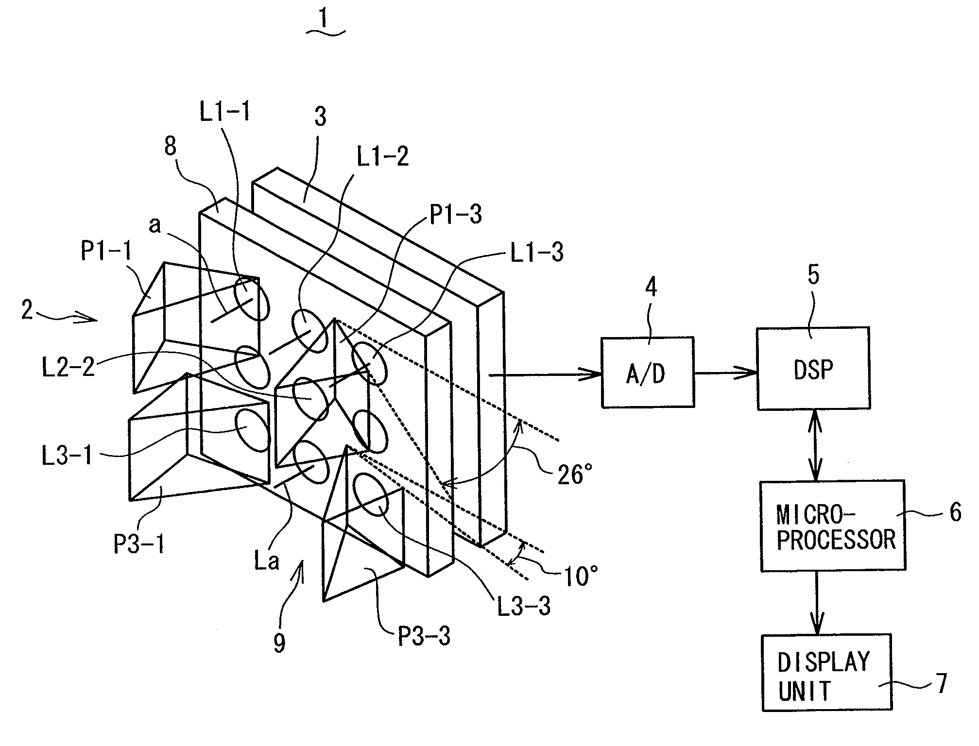
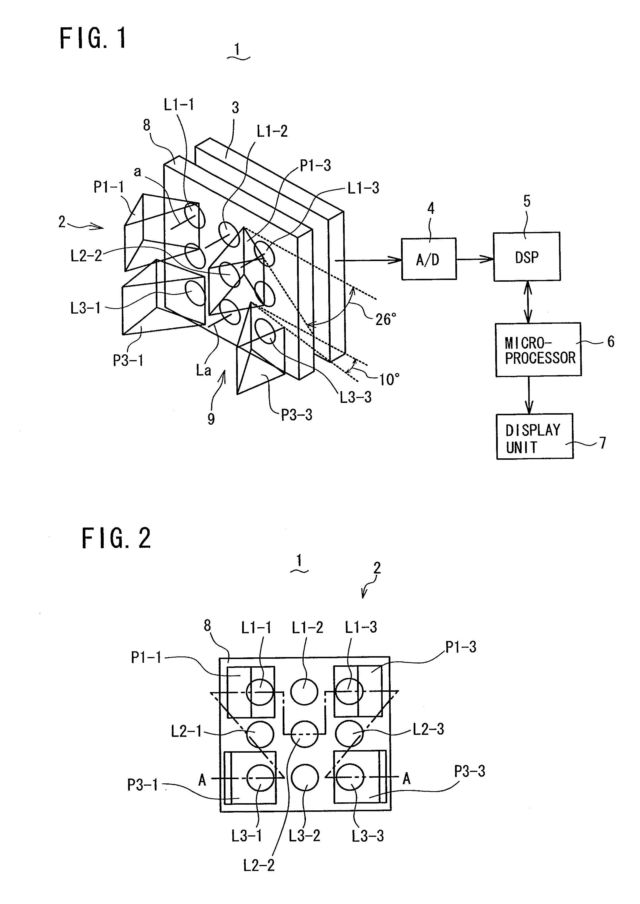
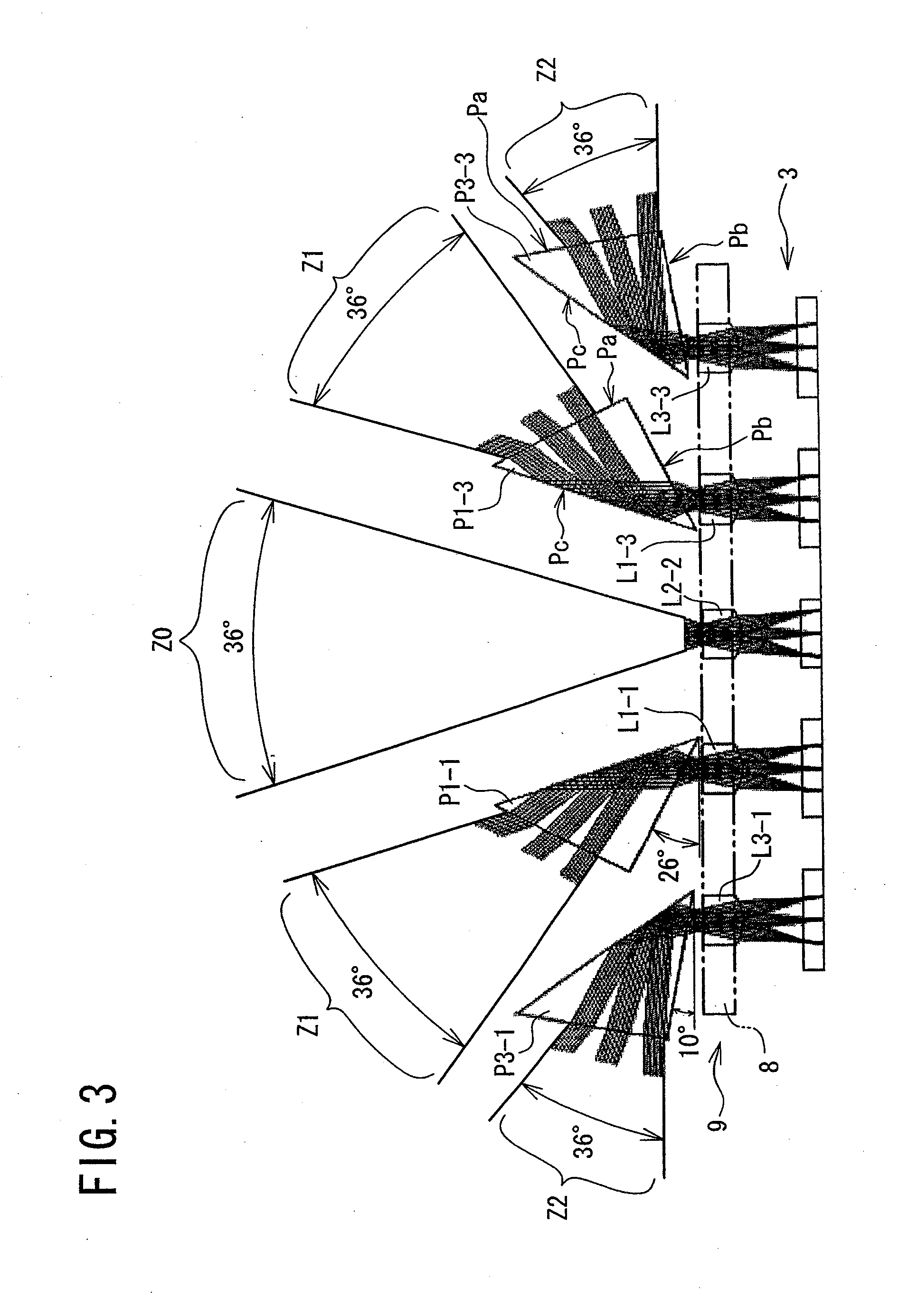
[0029]Referring to FIG. 1 to FIG. 5, a panoramic imaging device 1 according to an embodiment of the present invention will be described. As shown in FIG. 1 to FIG. 3, the panoramic imaging device 1 of the present embodiment comprises: an optical lens system 2 for collecting light entering therein in a capture angle (picture-taking angle) of at least 180° (approximately 180°) so as to form images on a predetermined focal plane; a photodetector array (claimed “imaging means”) 3 placed at the focal plane of the optical le...


PUM


Abstract

A panoramic imaging device comprises: a photodetector array; a lens array having, on one plane, a center lens for receiving light in a front range of 36° to form a central unit image on the photodetector array, and left and right side lenses for receiving lights in left and right ranges each of 72° in capture angle of 180°; and four prisms in two pairs placed facing the side lenses. The two pairs of left and right prisms (more inclined and less inclined pairs) collect lights in divided two pairs of left and right ranges each of 36° in the 72° range (pairs closer to, and farther from, the front range), respectively, to form four side unit images on the photodetector array which are combined with the central unit image to reproduce a panoramic image without using wide-angle lenses or complex image correction process.

Description

CROSS-REFERENCE TO RELATED APPLICATIONS[0001]This application is a divisional application of U.S. application Ser. No. 11 / 837,836 filed Aug. 13, 2007, the entire disclosure of which is herein expressly incorporated by reference. This application contains related subject matter to the Assignee's co-pending application Ser. Nos. 11 / 846,806, filed Aug. 29, 2007 and 11 / 736,267, filed Apr. 27, 2007BACKGROUND OF THE INVENTION[0002]1. Field of the Invention[0003]The present invention relates to a panoramic imaging device.[0004]2. Description of the Related Art[0005]Various devices for capturing images positioned therearound in a wide capture angle or range are known, such as a monitor camera and a monitoring system for monitoring obstacles around a car. For example, a known camera device for monitoring three directions around a car, that are front, left and right, uses prisms placed on the light entrance side of an imaging element, such that the prisms refract or bend lights entering in th...

Claims


Application Information

Patent Timeline
Patent Type & Authority Applications(United States)
IPC IPC(8): H04N7/00G03B15/00G03B37/00H04N5/225
CPCG02B13/06H04N5/23238H04N5/2254G03B37/04G02B27/1066H04N23/60H04N23/698
Inventor TOYODA, TAKASHINAKAO, YOSHIZUMIMASAKI, YASUO
Owner FUNAI ELECTRIC CO LTD
Why Eureka
Try Eureka