Electromagnetic interference (EMI) collar and method for use with a pluggable optical transceiver module

a technology of electromagnetic interference and optical transceiver, which is applied in the direction of coupling device connection, instrumentation, aperture leaage reduction, etc., can solve the problems of limited ability to reduce the spacing of transceiver modules, limited manufacturing techniques, and limited success of transceiver modules, so as to reduce the number of emi apertures and improve emi shielding

a technology of electromagnetic interference and optical transceiver, which is applied in the direction of coupling device connection, instrumentation, aperture leaage reduction, etc., can solve the problems of limited ability to reduce the spacing of transceiver modules, limited manufacturing techniques, and limited success of transceiver modules, so as to reduce the number of emi apertures and improve emi shielding

US20090196008A1Inactive Publication Date: 2009-08-06BROADCOM INT PTE LTD

Image

  • Electromagnetic interference (EMI) collar and method for use with a pluggable optical transceiver module
  • Electromagnetic interference (EMI) collar and method for use with a pluggable optical transceiver module
  • Electromagnetic interference (EMI) collar and method for use with a pluggable optical transceiver module

Examples


Embodiment Construction

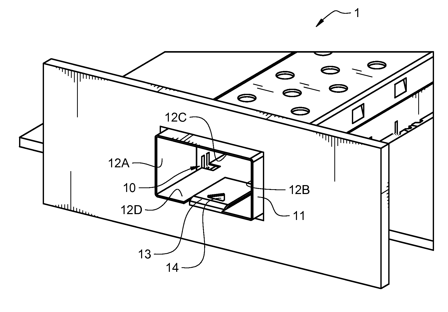
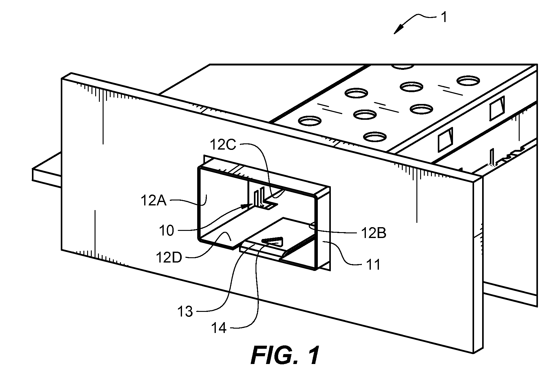
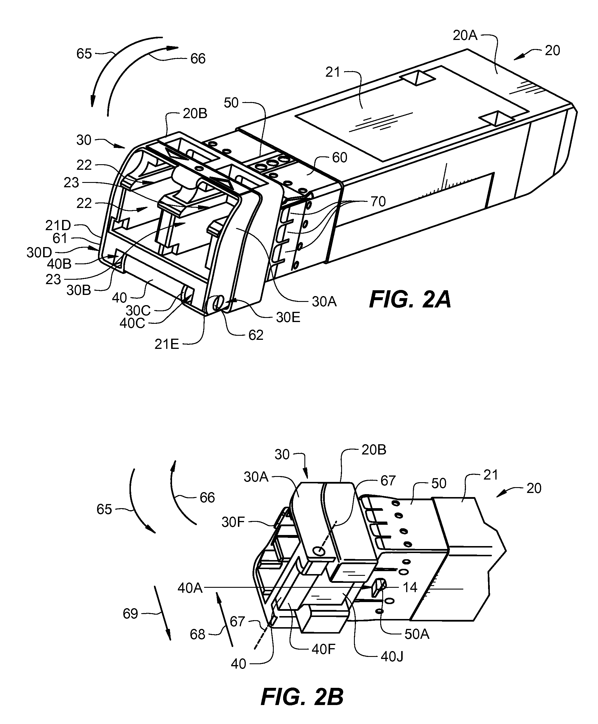
[0024]In accordance with various embodiments that will be described herein, an EMI collar is provided that is configured to be secured about a housing of a pluggable optical transceiver module. The configuration of the EMI collar and the method by which the collar is attached to the housing of the transceiver module ensure that the collar will not be damaged when the transceiver module housing is inserted into a cage. Ensuring that the collar will not be damaged during insertion ensures that the electrically conductive contact points on the collar will not be eliminated. In addition, dimples, or indentations, formed on the spring fingers of the EMI collar result in a reduction in the size of the maximum EMI aperture dimension, which greatly improves the ability of the collar to attenuate EMI signals, even those having high frequencies. The improvements in EMI signal attenuation result in an overall improvement in the performance of the transceiver module and in the performance of th...


PUM


Abstract

An EMI collar is provided that is configured to be secured about a housing of a pluggable optical transceiver module. The configuration of the EMI collar and the method by which the collar is attached to the housing of the transceiver module ensures that the collar will not be damaged when the transceiver module housing is inserted into a cage. Ensuring that the collar will not be damaged during insertion ensures that electrically conductive contact points on the collar will not be eliminated by insertion of the housing into a cage. In addition, dimples, or indentations, formed on the spring fingers of the EMI collar result in additional electrically conductive contact points on the fingers that result in a reduction in the size of the maximum EMI aperture dimension of the collar. Reducing the maximum EMI aperture dimension of the collar greatly improves the ability of the collar to attenuate EMI signals, even EMI signals having high frequencies.

Description

CROSS-REFERENCE TO RELATED APPLICATIONS[0001]This application is a continuation-in-part (CIP) application and claims the benefit of the filing date of currently pending U.S. application Ser. No. 12 / 027,027, filed on Feb. 6, 2008, entitled “AN ELECTROMAGNETIC INTERFERENCE (EMI) SYSTEM AND METHOD FOR USE WITH AN OPTICAL TRANSCEIVER MODULE”, which is incorporated by reference herein in its entirety.TECHNICAL FIELD OF THE INVENTION[0002]The invention relates to pluggable optical transceiver modules. More particularly, the invention relates to an electromagnetic interference (EMI) collar that attaches to a pluggable optical transceiver module and provides improved EMI shielding effectiveness.BACKGROUND OF THE INVENTION[0003]In optical communications networks, optical transceiver modules are used to transmit and receive optical signals over optical fibers. On the transmit side of a transceiver module, a light source (e.g., a laser diode) generates amplitude modulated optical signals that ...

Claims


Application Information

Patent Timeline
06 Aug 2009
Publication
US20090196008A1
IPC
H05K9/00; H01R13/648; H01R43/04
CPC
G02B6/4201; G02B6/4246; G02B6/4292; Y10T29/49218; H05K9/0018; H05K9/0058; Y10T29/49204; H01R13/65802
Inventors
MCCOLLOCH, LAURENCE R.