Electromagnetic interference (EMI) collar and method for use with a pluggable optical transceiver module

a technology of electromagnetic interference and optical transceiver, which is applied in the direction of coupling device connection, instrumentation, aperture leaage reduction, etc., can solve the problems of limited ability to reduce the spacing of transceiver modules, limited manufacturing techniques, and limited success of transceiver modules, so as to reduce the number of emi apertures and improve emi shielding

Inactive Publication Date: 2009-10-06
BROADCOM INT PTE LTD
View PDF7 Cites 32 Cited by
  • Summary
  • Abstract
  • Description
  • Claims
  • Application Information

AI Technical Summary

Benefits of technology

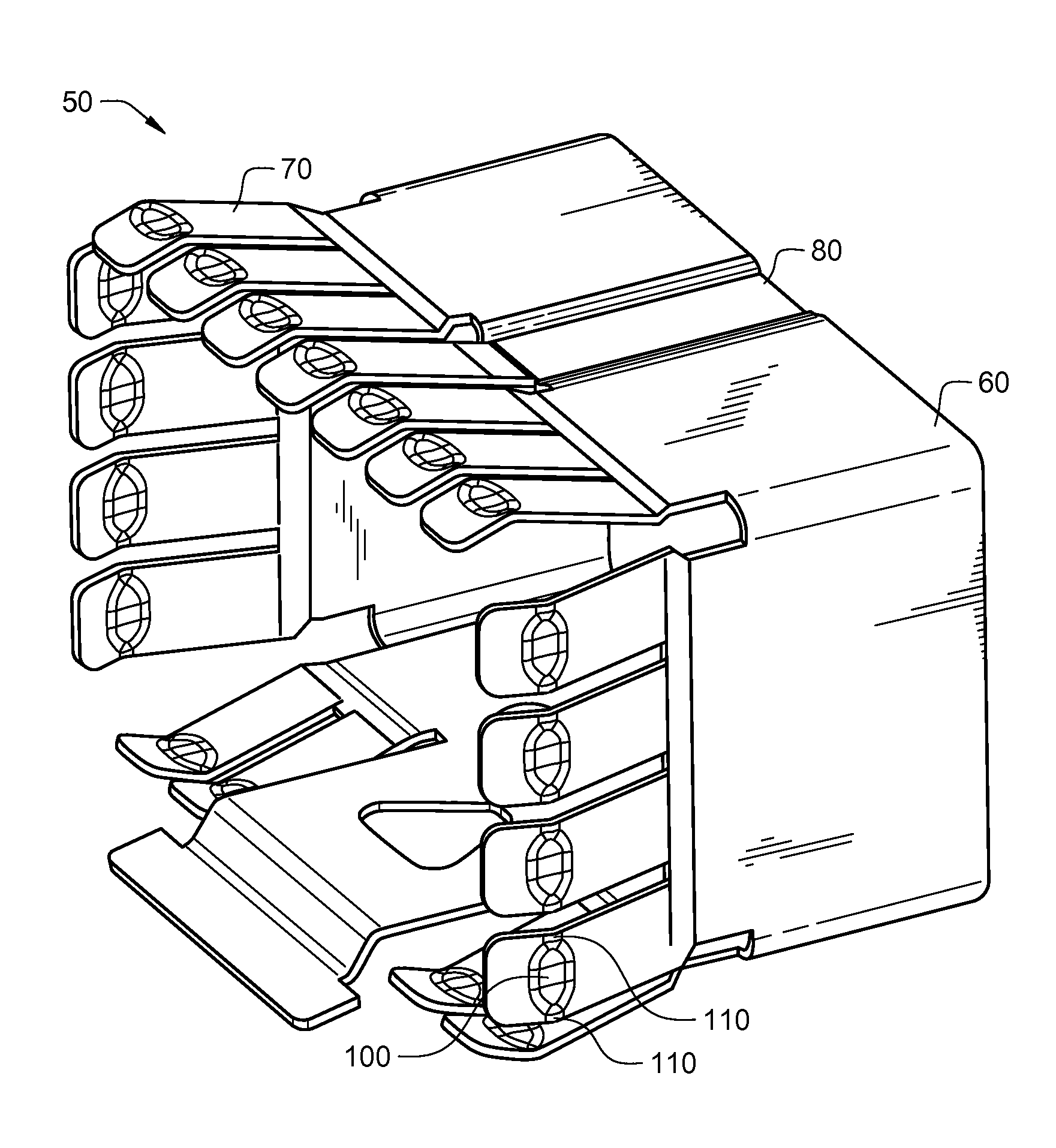
[0013]These additional contact points on the spring fingers are separated from each other by a distance that is generally equal to the length, L, of the respective dimple. Under normal operating conditions and absent any damage to or abnormalities in the collar, the length L will correspond to the maximum EMI aperture dimension of the collar. Consequently, the inclusion of the dimples on the fingers results in a reduction in the size of the maximum EMI aperture dimension of the collar, which improves the EMI shielding effectiveness of the collar. In addition, the reduction in the size of the maximum EMI aperture dimension of the collar enables EMI signals of high frequencies to be more easily shielded.
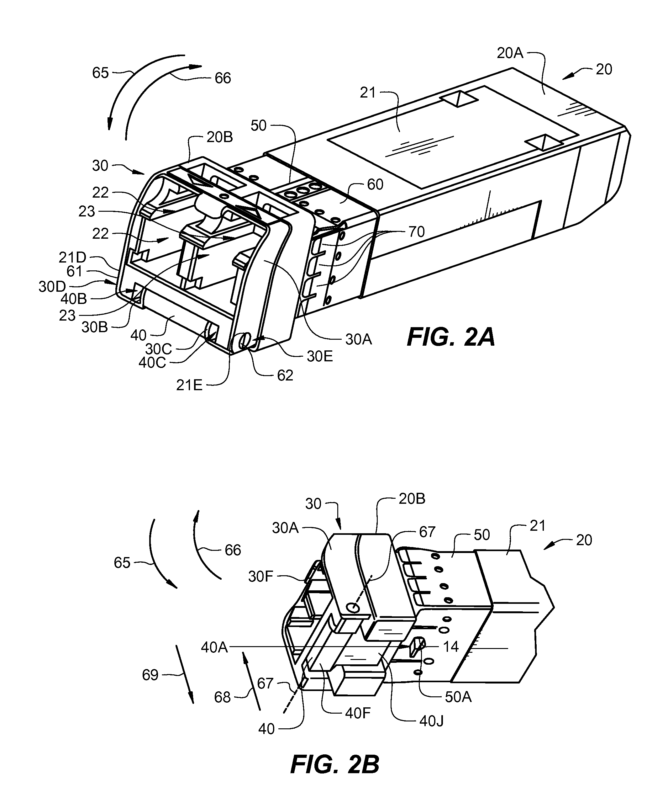
[0015]By welding the lap joint of the band to tighten the band about the housing of the transceiver module, the band is pre-loaded to cause the inner surface of the band to be placed in substantially continuous contact with the housing. This feature of the invention eliminates or at least lessens the number of EMI apertures that exist between the inner surface of the band and the outer surface of the housing, which improves EMI shielding. In addition, the tightness with which the band is secured to the housing eliminates or at least reduces the possibility of the collar being damaged when the housing having the collar secured about it is inserted into a cage, which also serves to improve EMI shielding.

Problems solved by technology

So far, such techniques and designs have had only limited success, especially with respect to transceiver modules that transmit and receive data at very high data rates (e.g., 10 gigabits per second (Gbits / sec)).
However, the ability to decrease this spacing using currently available manufacturing techniques is limited.
As the bit rates of these transceiver modules continue to increase, decreasing the spacing between spring fingers in order to improve EMI shielding effectiveness becomes less feasible, or impossible.
One of the problems associated with this method of attaching the collar is that it is susceptible to being damaged when the transceiver module housing having the collar secured thereto is inserted into a cage.
The elimination of any of these electrically conductive contact points results in a reduction in EMI shielding effectiveness, which degrades performance.

Method used


Image

  • Electromagnetic interference (EMI) collar and method for use with a pluggable optical transceiver module
  • Electromagnetic interference (EMI) collar and method for use with a pluggable optical transceiver module
  • Electromagnetic interference (EMI) collar and method for use with a pluggable optical transceiver module

Examples


Embodiment Construction

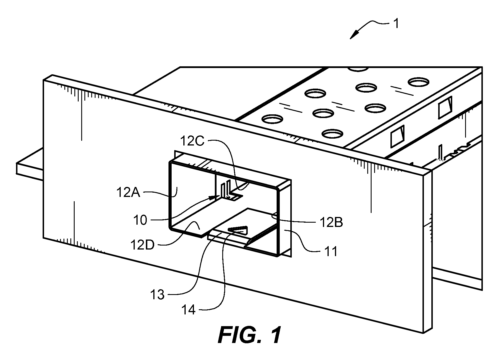
[0024]In accordance with various embodiments that will be described herein, an EMI collar is provided that is configured to be secured about a housing of a pluggable optical transceiver module. The configuration of the EMI collar and the method by which the collar is attached to the housing of the transceiver module ensure that the collar will not be damaged when the transceiver module housing is inserted into a cage. Ensuring that the collar will not be damaged during insertion ensures that the electrically conductive contact points on the collar will not be eliminated. In addition, dimples, or indentations, formed on the spring fingers of the EMI collar result in a reduction in the size of the maximum EMI aperture dimension, which greatly improves the ability of the collar to attenuate EMI signals, even those having high frequencies. The improvements in EMI signal attenuation result in an overall improvement in the performance of the transceiver module and in the performance of th...


PUM

PropertyMeasurementUnit
electrically conductiveaaaaaaaaaa
lengthaaaaaaaaaa
areasaaaaaaaaaa

Abstract

An EMI collar is provided that is configured to be secured about a housing of a pluggable optical transceiver module. The configuration of the EMI collar and the method by which the collar is attached to the housing of the transceiver module ensures that the collar will not be damaged when the transceiver module housing is inserted into a cage. Ensuring that the collar will not be damaged during insertion ensures that electrically conductive contact points on the collar will not be eliminated by insertion of the housing into a cage. In addition, dimples, or indentations, formed on the spring fingers of the EMI collar result in additional electrically conductive contact points on the fingers that result in a reduction in the size of the maximum EMI aperture dimension of the collar. Reducing the maximum EMI aperture dimension of the collar greatly improves the ability of the collar to attenuate EMI signals, even EMI signals having high frequencies.

Description

CROSS-REFERENCE TO RELATED APPLICATIONS[0001]This application is a continuation-in-part (CIP) application and claims the benefit of the filing date of currently pending U.S. application Ser. No. 12 / 027,027, filed on Feb. 6, 2008, entitled “AN ELECTROMAGNETIC INTERFERENCE (EMI) SYSTEM AND METHOD FOR USE WITH AN OPTICAL TRANSCEIVER MODULE”, which is incorporated by reference herein in its entirety.TECHNICAL FIELD OF THE INVENTION[0002]The invention relates to pluggable optical transceiver modules. More particularly, the invention relates to an electromagnetic interference (EMI) collar that attaches to a pluggable optical transceiver module and provides improved EMI shielding effectiveness.BACKGROUND OF THE INVENTION[0003]In optical communications networks, optical transceiver modules are used to transmit and receive optical signals over optical fibers. On the transmit side of a transceiver module, a light source (e.g., a laser diode) generates amplitude modulated optical signals that ...

Claims


Application Information

Patent Timeline
Patent Type & Authority Patents(United States)
IPC IPC(8): H01R13/648
CPCG02B6/4201G02B6/4292H05K9/0018H05K9/0058G02B6/4246Y10T29/49218Y10T29/49204H01R13/65802G02B6/4261G02B6/4277H01R13/6582G02B6/4293H05K9/0009H05K9/0016
Inventor MCCOLLOCH, LAURENCE R.
Owner BROADCOM INT PTE LTD
Why Eureka
Try Eureka