
Shielded connector

A connector and mating connector technology, which is applied in the connection, the parts of the connecting device, the protective grounding/shielding device of the connecting parts, etc., can solve the problems of interference signals, electromagnetic interference, etc., to reduce the shielding porosity and improve the electrical contact. , the effect of reducing the height

Inactive Publication Date: 2011-10-12
FRAMATOME CONNECTORS INT SA
View PDF4 Cites 6 Cited by
  • Summary
  • Abstract
  • Description
  • Claims
  • Application Information

AI Technical Summary

Problems solved by technology

Such EMI radiation may cause electromagnetic interference to other adjacent connector components and / or electrical or electronic devices
Vice versa, electromagnetic radiation emitted through the connector environment may interfere with the signal transmitted by the connector

Method used


Image

  • Shielded connector
  • Shielded connector
  • Shielded connector

Examples


Embodiment Construction

[0043] In the drawings, the same objects and elements are denoted by the same reference signs.

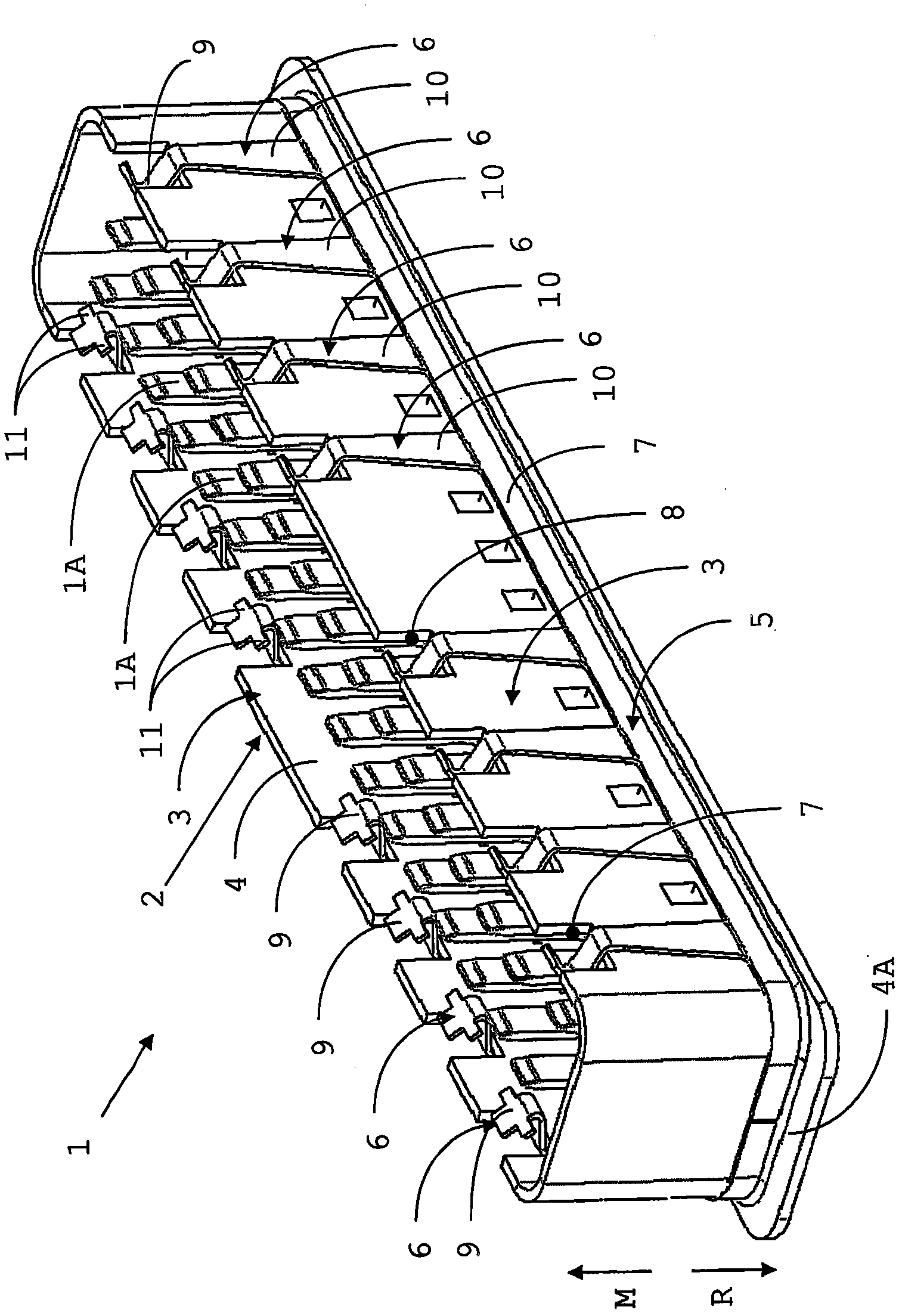
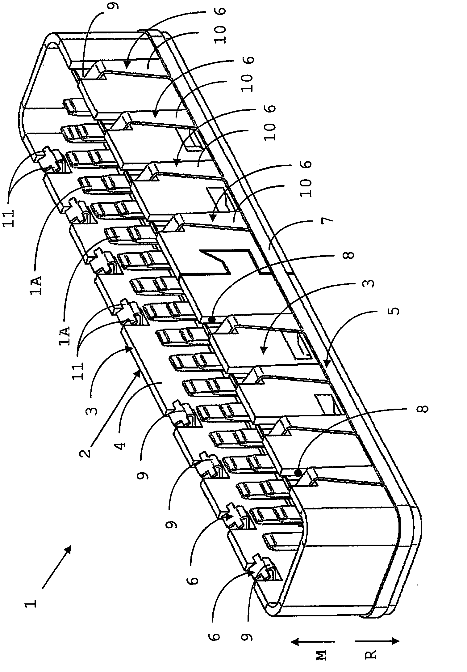
[0044] figure 1 with 2 Two similar embodiments of a connector 1 of a connector assembly comprising a connector and a mating connector (not shown in the figures) are shown. The connector 1 includes a plurality of contact terminals 1A and a shield assembly 2 . The connector 1 has a mating side facing a mating direction M and a back side facing an opposite direction R, as figure 1 indicated by the arrow in .

[0045] The shielding assembly 2 comprises a shielding member 3 having a shielding wall 4 . The shielding assembly 2 also includes a resilient member 5 comprising a plurality of resilient elements 6 coupled by carrying strips 7 .

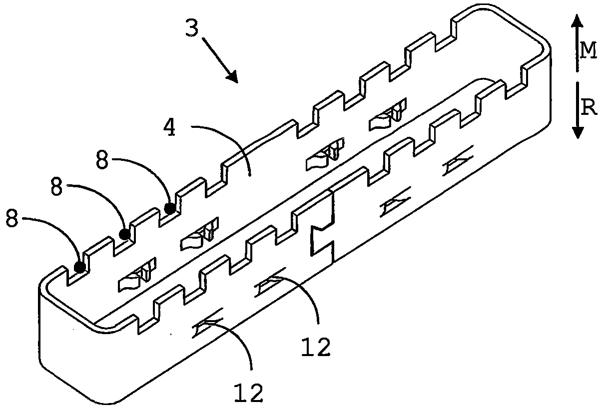
[0046] figure 1 The shielding member 3 of the embodiment is a one-piece object comprising a shielding wall 4 and a mounting flange 4A on the rear side. This shielding member 3 is suitably manufactured by a technique such as deep drawing.

[004...


PUM


Abstract

The present invention provides a shielding assembly (2) for a connector assembly comprising a connector (1) and a counterpart connector (100). The shielding assembly comprises a shield member (3) having a shield wall (4) and at least one spring element (6) for making electrical contact between the shield wall and the counterpart connector along a first electrical conduction path in the mated situation of the connector and the counterpart connector. The spring element comprises a first portion (9) being configured for making electrical contact with the counterpart connector and a second portion (10) for providing a spring force to the first portion. The spring element is configured for having at least a first position in the unmated situation of the connector and the counterpart connector and a second position in the mated situation of the connector and the counterpart connector, such that in the first position the second portion is arranged at a first separation from the shield wall and in the second position the second portion is arranged at a second separation from the shield wall, wherein the second separation is larger than the first separation.

Description

technical field [0001] The present invention generally relates to structures for preventing or shielding electromagnetic interference ("EMI") radiation from connector assemblies. In particular, the present invention relates to shielding electrical connectors and shielding assemblies for connectors for high speed signal transmission. Background technique [0002] Connector assemblies may be used in or between electronic devices for transmitting signals between two cables or between a cable and a printed circuit board of an electronic device. The usual approach is to interconnect them with a connector assembly comprising one connector configured to at least partially mate with another connector or a mating connector. [0003] It is widely known that signals transmitted through such connector assemblies can result in EMI emissions. This is especially the case for high-speed and / or high-frequency signals, eg, about 1 GB per second or higher, and the consequences of increasing ...

Claims


Application Information

Patent Timeline
Patent Type & Authority Applications(China)
IPC IPC(8): H01R13/6582H01R13/658
CPCH01R13/6582
Inventor R·T·德布利克M·丰特诺
Owner FRAMATOME CONNECTORS INT SA
Learn More