
Controlled impedance display adapter

a display adapter and impedance control technology, applied in the direction of static indicating devices, coupling device connections, instruments, etc., can solve the problems of large majority of displays in the installed base that cannot natively accept dvi-i cables, and the majority of displays in the installed base cannot. , to achieve the effect of improving the emi shielding of the device, reducing costs, and precise quality control of manufacturing processes

Inactive Publication Date: 2011-09-20
NVIDIA CORP
View PDF162 Cites 4 Cited by
  • Summary
  • Abstract
  • Description
  • Claims
  • Application Information

AI Technical Summary

Benefits of technology

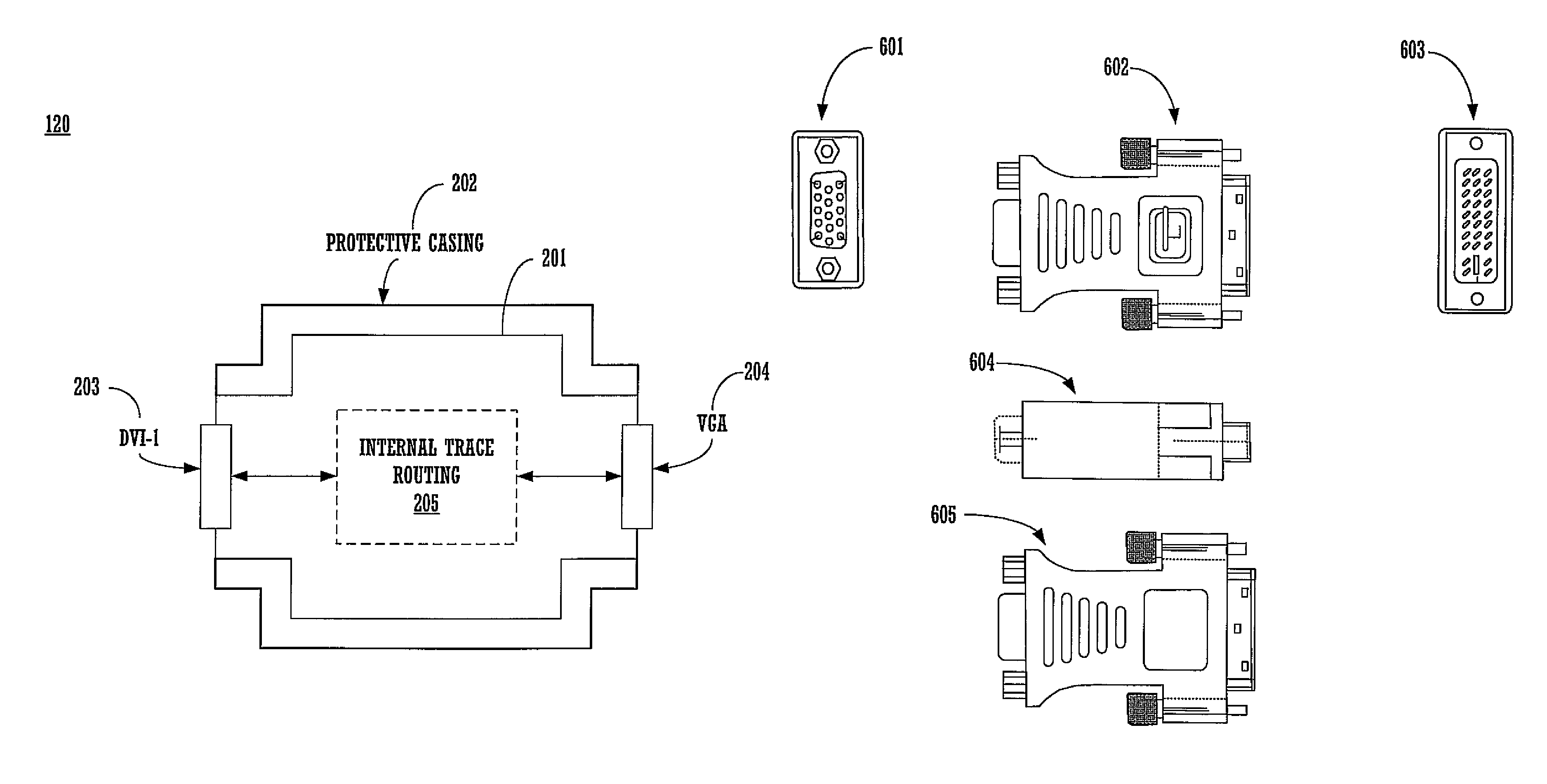
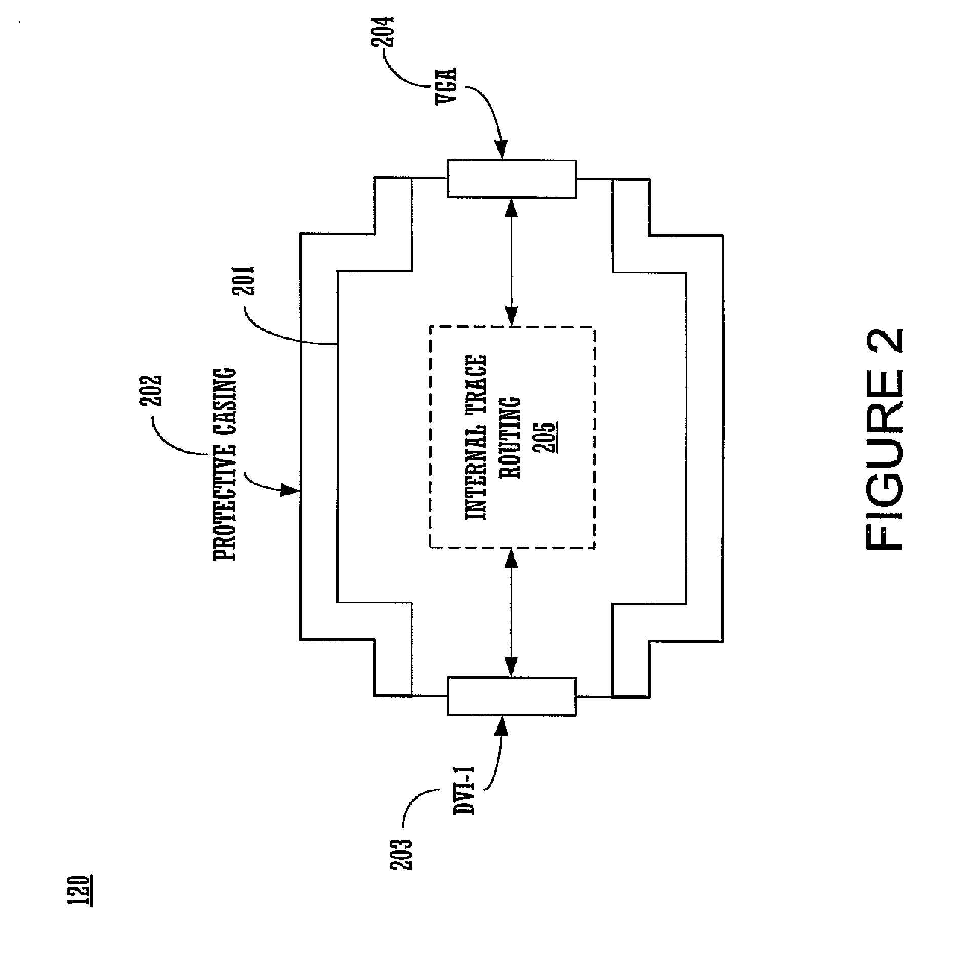
[0010]Embodiments of the present invention comprise an efficient device to adapter signals and interconnect a DVI-I connector, DVI-D connector HDMI connector and VGA connector. Embodiments of the present invention eliminate the need for any intricate internal wiring and soldering of signal lines, and provides precise control over signal trace length and impedance. Embodiments of the present invention maintain high-quality signal characteristics for high-quality displays and provides greatly improved EMI shielding.
[0013]The dual shielding of the device case enclosure and the PCB greatly improves EMI shielding of the device in comparison to the prior art. Additionally, the use of PCB manufacturing techniques enable precise quality control of the manufacturing processes and leverages the widespread PCB manufacturing infrastructure to reduce costs.

Problems solved by technology

A problem exists however with respect to the fact that the great majority of the displays existing in the installed base (e.g., the displays that have been purchased within the past 10 years and are still in use) are not compatible with digital DVI.
But the great majority of the displays in the installed base cannot natively accept a DVI-I cable.
This solution is less than satisfactory due to the fact that the prior art dongles require intricate internal wiring and soldering in order to physically couple the signal lines for the analog DVI-I signal to the VGA signal.
These requirements make proper quality control of the often labor-intensive manufacturing processes for the prior art type dongle difficult.
Low-cost manufacturing techniques often yield sub-par components.
High-quality components can only be obtained (if at all) at a high cost.

Method used


Image

  • Controlled impedance display adapter
  • Controlled impedance display adapter
  • Controlled impedance display adapter

Examples


Embodiment Construction

[0021]Reference will now be made in detail to the preferred embodiments of the present invention, examples of which are illustrated in the accompanying drawings. While the invention will be described in conjunction with the preferred embodiments, it will be understood that they are not intended to limit the invention to these embodiments. On the contrary, the invention is intended to cover alternatives, modifications and equivalents, which may be included within the spirit and scope of the invention as defined by the appended claims. Furthermore, in the following detailed description of embodiments of the present invention, numerous specific details are set forth in order to provide a thorough understanding of the present invention. However, it will be recognized by one of ordinary skill in the art that the present invention may be practiced without these specific details. In other instances, well-known methods, procedures, components, and circuits have not been described in detail ...


PUM


Abstract

A display adapter for a digital connector and an analog connector. The display adapter includes a PCB (printed circuit board). A first connector and a second connector are both mounted on the PCB. The first connector and second connectors can be VGA, DVI-I, DVI-D, or HDMI format. The PCB is configured to communicatively couple video signals between the first connector having one format and the second connector having a different format.

Description

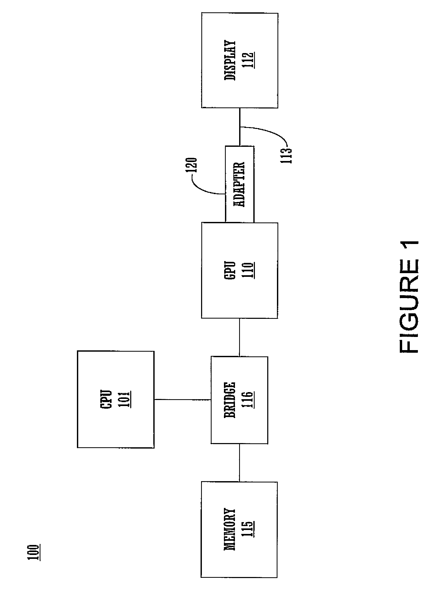
[0001]This Application is a Divisional of U.S. patent application Ser. No. 11 / 114,347, filed Apr. 25, 2005, entitled “A CONTROLLED IMPEDANCE DISPLAY ADAPTER” to Ross Jatou, et al., which is hereby incorporated herein in its entirety.FIELD OF THE INVENTION[0002]The present invention is generally related to high performance display interconnects for computer systems.BACKGROUND OF THE INVENTION[0003]Modern computer systems feature powerful digital processor integrated circuit devices. The processors are used to execute software instructions that implement complex functions, such as, for example, real-time 3-D graphics applications, photo-retouching and photo editing, data visualization, and the like. The performance of many these graphics-reliant applications is directly benefited by more powerful graphics processors which are capable of accurately displaying large color depths (e.g., 32 bits, etc.), high resolutions (e.g., 1900×1200, 2048×1536 etc.), and are thus able to more clearly ...

Claims


Application Information

Patent Timeline
Patent Type & Authority Patents(United States)
IPC IPC(8): H01R25/00
CPCH01R31/065G09G5/006H01R13/6658H01R2201/06
Inventor JATOU, ROSS F.SHU, CHARLIE J.SUBRAMAN, NANDAN
Owner NVIDIA CORP
Learn More