Planar lighting device

a lighting device and planar technology, applied in lighting device details, lighting and heating apparatus, instruments, etc., can solve the problems of uneven light distribution and difficulty in achieving a thickness of 10 mm or less with a direct illumination type backlight unit, and achieve the effect of increasing dimensions

Active Publication Date: 2009-08-06
FUJIFILM CORP
View PDF6 Cites 63 Cited by
  • Summary
  • Abstract
  • Description
  • Claims
  • Application Information

AI Technical Summary

Benefits of technology

[0036]According to the planar lighting device of the present invention, light launched through the light entrance plane can reach a farther position in a light guide plate having a light entrance plane that is thin in a direction perpendicular to the light exit plane. This makes it possible to emit uniform illumination light free from brightness unevenness and achieve a thin, lightweight design with increased dimensions.
[0037]Further, the planes on both sides of the light guide plate may be used as light exit plane, emitting light through both the first light exit plane and the second light exit plane, the latter being on the side opposite from the former.

Problems solved by technology

While demands of still thinner backlight units are expected to grow in the future, achieving a thickness of 10 mm or less with a direct illumination type backlight unit is deemed difficult in view of uneven light amount distribution expected to accompany that type.

Method used


Image

  • Planar lighting device
  • Planar lighting device
  • Planar lighting device

Examples


first embodiment

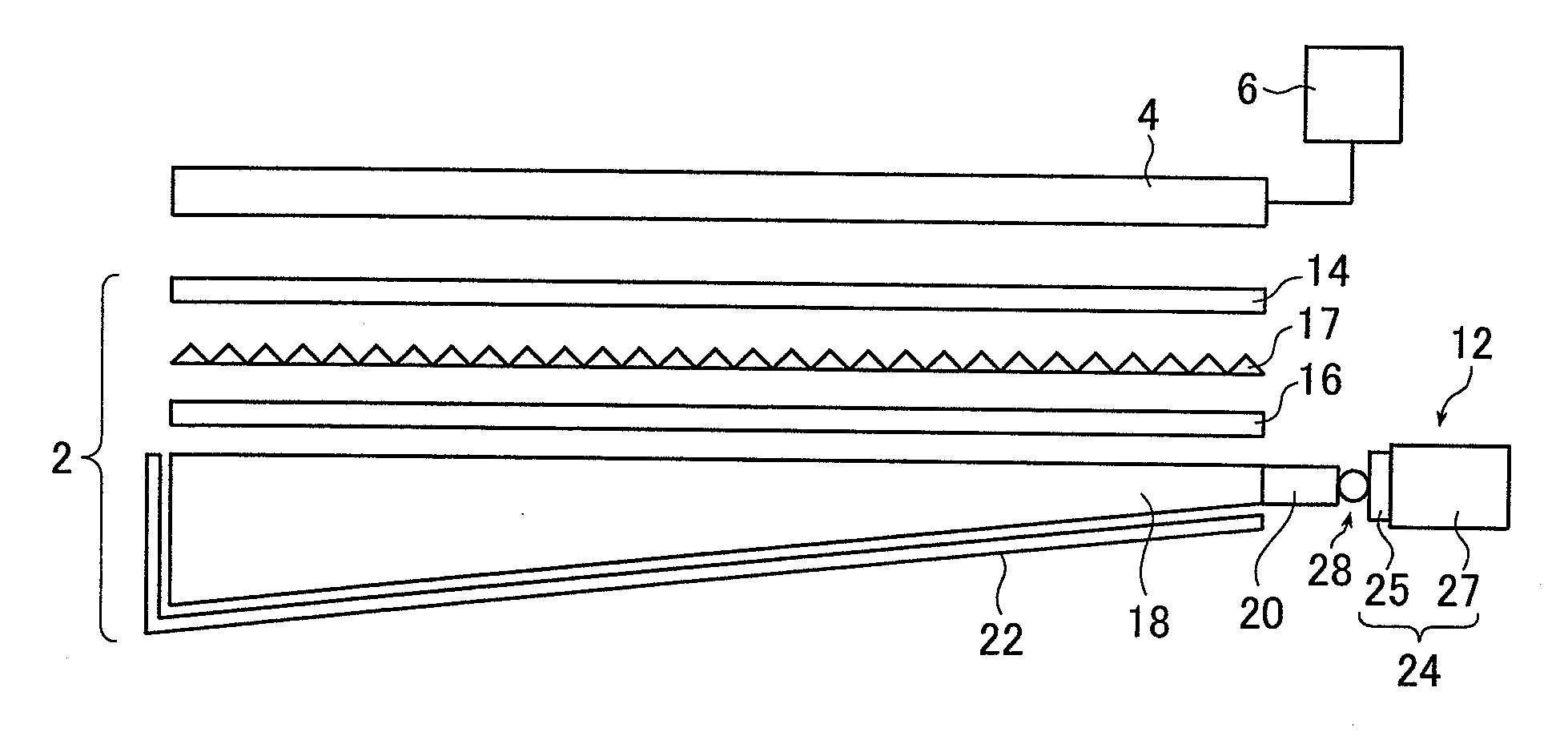
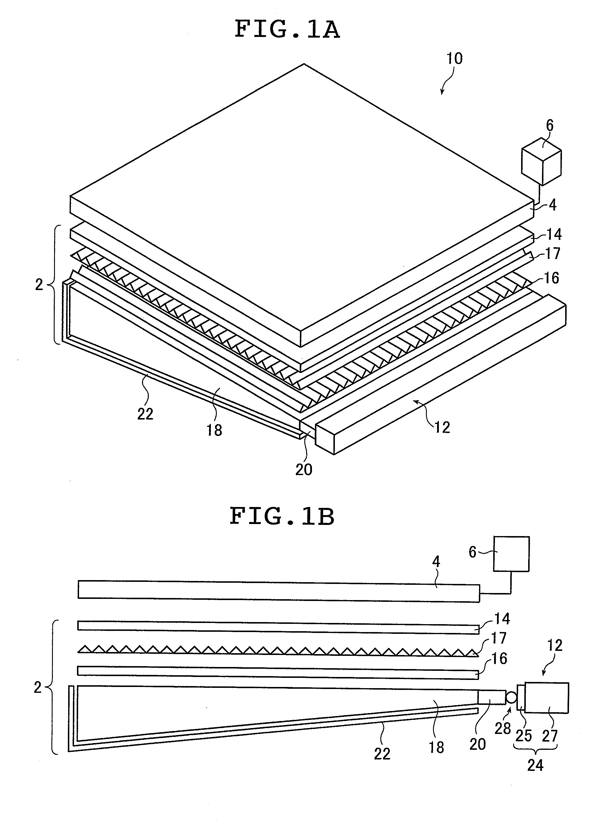
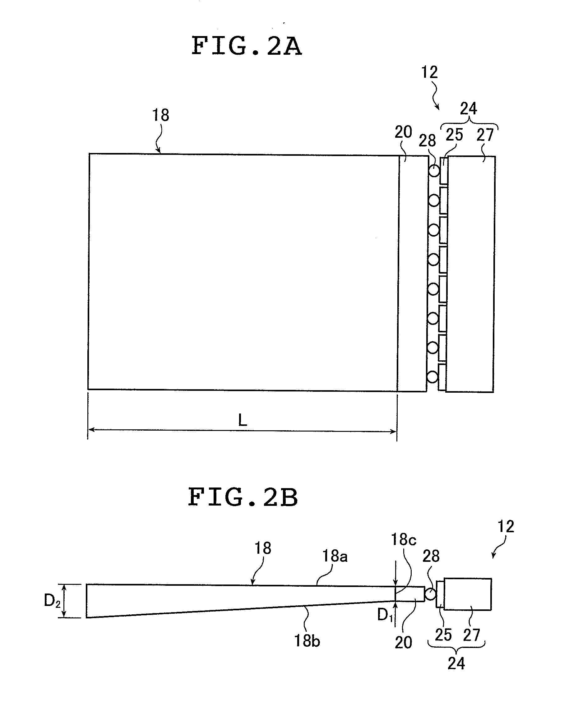
[0096]FIG. 1A is a schematic perspective view of a liquid crystal display device provided with the planar lighting device according to the present invention; FIG. 1B is a schematic sectional view of the liquid crystal display device. FIG. 2A is a schematic plan view of a light guide plate and a light source used in the inventive planar lighting device (hereinafter referred to as backlight unit); FIG. 2B is a schematic sectional view of the light guide plate.

[0097]A liquid crystal display device 10 comprises a backlight unit 2, a liquid crystal display panel 4 disposed on the side of the backlight unit closer to the light exit plane, and a drive unit 6 for driving the liquid crystal display panel 4.

[0098]In the liquid crystal display panel 4, electric field is partially applied to liquid crystal molecules previously arranged in a given direction to change the orientation of the molecules. The resultant changes in refractive index in the liquid crystal cells are used to display charac...

second embodiment

[0249]Now, the inventive planar lighting device will be described.

[0250]While, in the first embodiment described above, one rectangular plane of the light guide plate is used as a light exit plane, two planes may be adapted to serve as light exit planes such that the light exit plane as so referred to above is a first light exit plane and the plane opposite to the first exit plane is a second light exit plane, thus emitting light through both planes.

[0251]FIG. 15 is a sectional view schematically illustrating a configuration of a planar lighting device (backlight unit) 100 according to the second embodiment. Note that the same components shared by the backlight unit 10 illustrated in FIGS. 1 and 2 are given like reference characters, omitting detailed description thereof. Thus, description below will focus upon unshared components.

[0252]The backlight unit 100 comprises the light source 12, the diffusion film 14 and 102, prism sheets 16, 17, 104, and 106, the light guide plate 80, th...

third embodiment

[0265]Now, the inventive planar lighting device will be described.

[0266]FIG. 17 is a schematic sectional view illustrating a configuration of a planar lighting device (backlight unit) 140 according to the third embodiment. Note that in the backlight unit 140 of FIG. 17, the same components shared by the backlight unit 10 illustrated in FIGS. 1 and 2 are given like reference characters, omitting detailed description thereof. Thus, description below will focus upon unshared components.

[0267]The backlight unit 140 comprises a light source 142, the diffusion film 14, the prism sheets 16 and 17, a light guide plate 144, and a reflection film 22.

[0268]The light source 142 are substantially the same as the LED array 24 of FIG. 3.

[0269]The light guide plate 144 comprises a flat, substantially rectangular light exit plane 144a, an inclined plane 144b located on the side opposite from the light exit plane 144a and inclined a given angle with respect to the light exit plane 144a, and a light e...


PUM


Abstract

Provided is a thin, lightweight planar lighting device capable of emitting uniform illumination light free from brightness unevenness and enabling increase in dimensions. The device includes a light source and a light guide plate disposed opposite to the light source, and the light guide plate includes a light entrance plane opposite to the light source and a light exit plane containing one side of the light entrance plane, and has a shape growing thicker in direction perpendicular to the light exit plane with the increasing distance from the light entrance plane and contains scattering particles for scattering light entering through the light entrance plane and propagating the inside thereof.

Description

TECHNICAL FIELD[0001]The present invention relates to a planar lighting device used in liquid crystal display devices and the like.BACKGROUND ART[0002]Liquid crystal display devices use a backlight unit for radiating light from behind the liquid crystal display panel to illuminate the liquid crystal display panel. A backlight unit is configured using a light guide plate for diffusing light emitted by an illumination light source to irradiate the liquid crystal display panel and parts such as a prism sheet and a diffusion sheet for uniforming the light emitted from the light guide plate.[0003]Currently, large liquid crystal televisions predominantly use a so-called direct illumination type backlight unit comprising a light guide plate disposed immediately above the illumination light source. This type of backlight unit comprises a plurality of cold cathode tubes serving as a light source provided behind the liquid crystal display panel whereas the inside of the backlight unit provide...

Claims


Application Information

Patent Timeline
Patent Type & Authority Applications(United States)
IPC IPC(8): F21V7/22
CPCG02B6/0041G02B6/0046G02B6/0061G02B6/0063G02F2001/133342G02B6/0073G02B6/0078G02B6/0083G02B6/0085G02B6/0068G02F1/133342F21V7/09
Inventor IWASAKI, OSAMU
Owner FUJIFILM CORP
Why Eureka
Try Eureka