Check patentability & draft patents in minutes with Patsnap Eureka AI!

Signal processing method and circuit to convert analog signal to digital signal

a signal processing and digital signal technology, applied in the direction of synchronising signal speed/phase control, instruments, television systems, etc., can solve the problems of blurred image, inability to obtain phase information, and insufficient sampling, so as to improve signal quality

Inactive Publication Date: 2009-08-06
RENESAS ELECTRONICS CORP
View PDF4 Cites 13 Cited by
  • Summary
  • Abstract
  • Description
  • Claims
  • Application Information

AI Technical Summary

Benefits of technology

[0043]The present invention can adjust a phase of a sampling clock more securely and more accurately than the above related technique [2] without depending on a signal waveform. Therefore, it is possible to improve a signal quality (a display quality in a digital image display, for example) in various apparatuses to apply the present invention to.

Problems solved by technology

However, under the condition that the delays (input timings) of RGB signals and their synchronizing signals are not the same, the following problem has occurred.
Specifically, sampling is not performed appropriately by use of a sampling clock generated in response to such synchronizing signals as triggers, and consequently a blurred image is obtained when the resultant digital image signals are displayed.
However, such a signal processing circuit has a problem that an adjusted phase of a sampling clock varies depending on the set value of the threshold value Th.
The above related technique [2] has a problem that although the accuracy of adjusting a sampling clock is increased by selecting a phase with which a maximum value is obtained among maximum differences, the accuracy of the adjustment depends on the waveform of a digital signal, that is, an analog signal before conversion.
Therefore, it is not possible to obtain any information for adjusting a phase since maximum values of the maximum differences Dn_max do not change even when the phase of a sampling clock is caused to change.

Method used


Image

  • Signal processing method and circuit to convert analog signal to digital signal
  • Signal processing method and circuit to convert analog signal to digital signal
  • Signal processing method and circuit to convert analog signal to digital signal

Examples


first exemplary embodiment

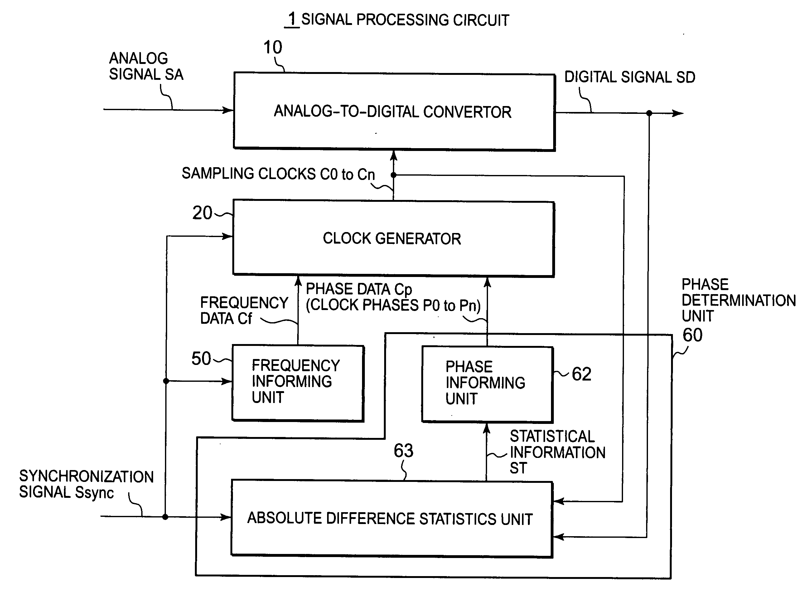
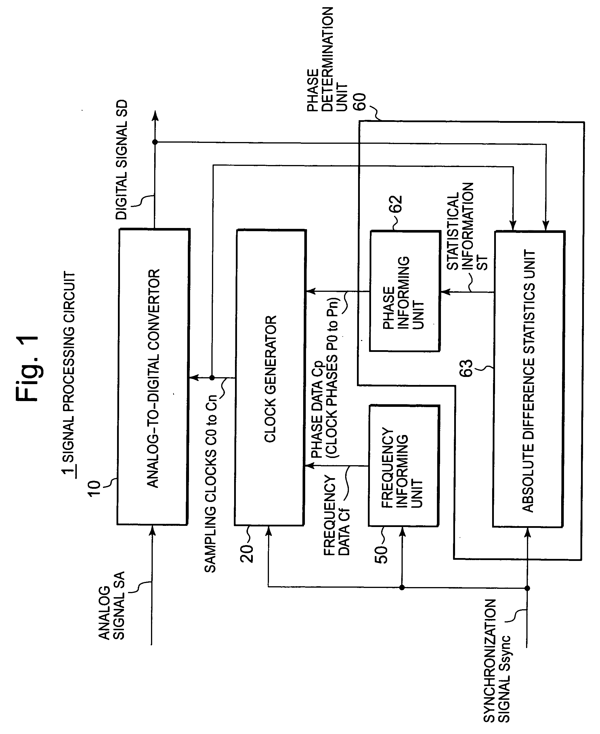
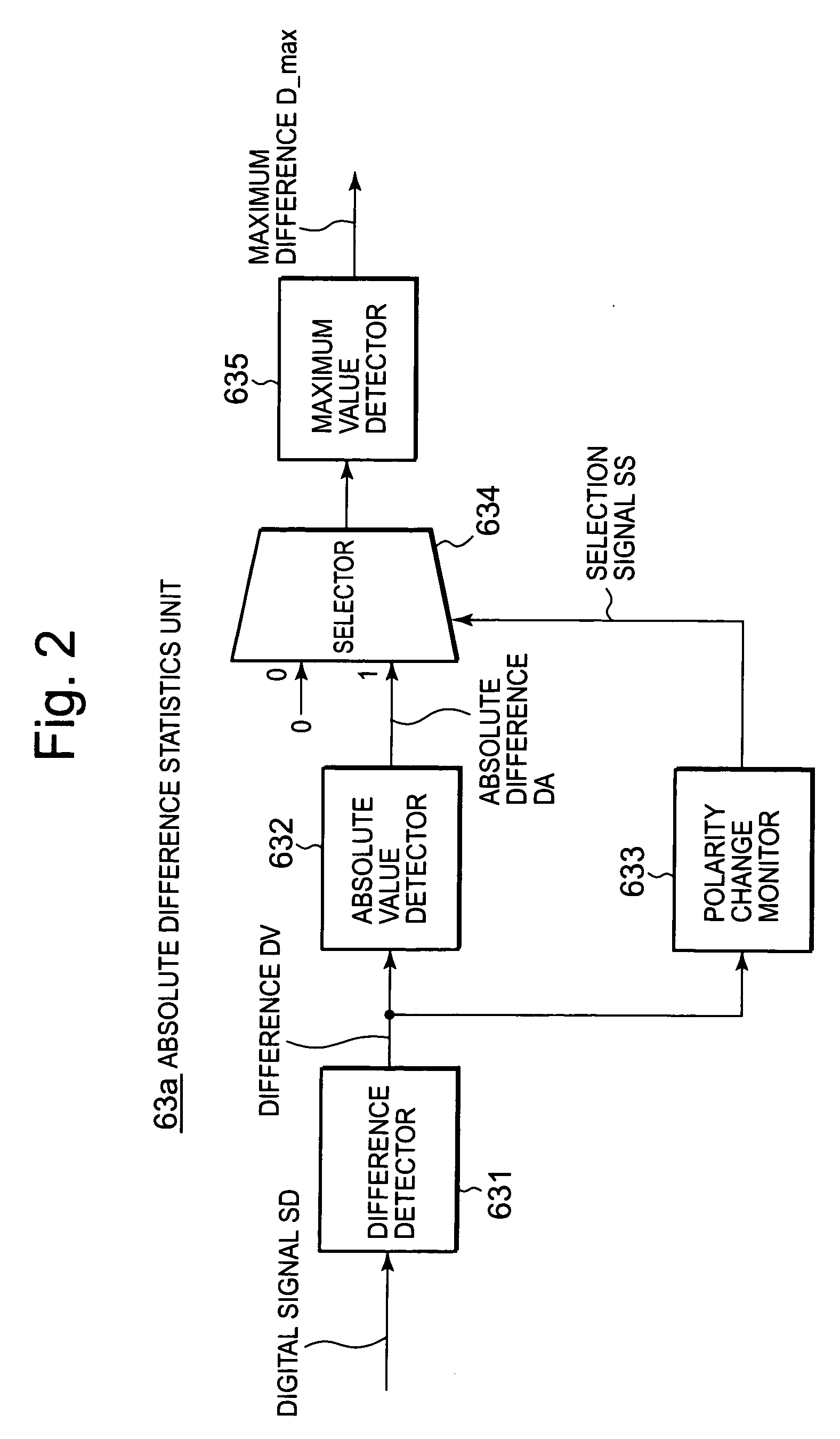
[0065]As shown in FIG. 2, a maximum difference statistics unit 63a used in this exemplary embodiment has: a difference detector 631 which detects differences DV between each adjacent two signal levels in each digital signal SD sequentially sampled by sampling clocks C0 to Cn; an absolute value detector 632 which detects absolute values DA of the differences DV; a polarity change monitor 633 which monitors a polarity change in the differences DV and generates a selection signal SS (“1” or “0”); a selector 634 which selects, in accordance with the selection signal SS, either the absolute difference DA inputted from the absolute value detector 632 or “0” always inputted; and a maximum value detector 635 which detects a maximum value D_max of an output from the selector 634 and provides the phase informing unit 62 with the maximum value as the statistical information ST shown in FIG. 1.

[0066]In other words, only when detecting the polarity change in the absolute difference DA, the polar...

second exemplary embodiment

[0076]A maximum difference statistics unit 63b shown in FIG. 5 and used in this exemplary embodiment is different from the maximum difference statistics unit 63a in the above first exemplary embodiment in that, instead of the maximum value detector 635 shown in FIG. 2, an accumulator 636 is provided which adds up the absolute differences DA where the polarity change has been detected, which finds the total sum (hereinafter, referred to as the difference total sum) SUM and which provides the phase informing unit 62 with the sum as the statistical information ST shown in FIG. 1.

[0077]With regard to the operations, the accumulator 636 provides the phase informing unit 62 with difference total sums SUM0 to SUMn found by sequentially adding up the absolute differences DA for the sampling clocks C0 to Cn. The phase informing unit 62 extracts a clock phase corresponding to a minimum value among the difference total sums SUM0 to SUMn as an inappropriate phase, as well as determines an antip...

third exemplary embodiment

[0080]A maximum difference statistics unit 63c shown in FIG. 6 and used in this exemplary embodiment is different from the maximum difference statistics unit 63a in the above first exemplary embodiment in that, instead of the maximum value detector 635 shown in FIG. 2, a minimum value detector 637 is provided which detects a minimum value D_min of the absolute difference DA (hereinafter, referred to as the minimum difference) where the polarity change has been detected and which provides the phase informing unit 62 with the minimum difference as the statistical information ST shown in FIG. 1.

[0081]With regard to the operations, the minimum value detector 637 sequentially detects the minimum differences D0_min to Dn_min for the sampling clocks C0 to Cn and provides the minimum differences to the phase informing unit 62. The phase informing unit 62 extracts a clock phase corresponding to a minimum value among the minimum differences D0_min to Dn_min as an inappropriate phase, as well ...


PUM


Abstract

A phase determination unit in a signal processing circuit generates sampling clocks with different phases in a clock generator and sequentially provides them to an analog-to-digital convertor. Then, the phase determination unit obtains differences between each adjacent two signal levels in each sampled digital signal by use of the sampling clocks, and monitors a polarity change in the differences, extracts a more inappropriate phase for use in sampling from phases of the sampling clocks on the basis of the absolute values of the differences where the polarity change is detected, and determines an antiphase of the extracted phase as a phase of the sampling clock to be provided to the analog-to-digital convertor.

Description

BACKGROUND OF THE INVENTION[0001]1. Field of the Invention[0002]The present invention relates to a signal processing method and a signal processing circuit, and particularly relates to a method and a circuit for automatically adjusting a phase of a sampling clock used when sampling an analog signal and converting the signal to a digital signal.[0003]2. Description of Related Art[0004]In a digital image display apparatus and the like, an analog-to-digital convertor samples (quantizes) RGB (Red-Green-Blue) signals being image data by use of a sampling clock, and thereby converts the signals to digital image signals. Here, generation of the sampling clock for the RGB signals is triggered by their synchronizing signals (a horizontal synchronizing signal and a vertical synchronizing signal). However, under the condition that the delays (input timings) of RGB signals and their synchronizing signals are not the same, the following problem has occurred. Specifically, sampling is not perform...

Claims


Application Information

Patent Timeline
Patent Type & Authority Applications(United States)
IPC IPC(8): H04L7/04
CPCG09G5/008H04N5/126H04N5/06G09G3/20G09G3/36H04N5/66
Inventor YAMASHITA, KENJI
Owner RENESAS ELECTRONICS CORP
Features
  • R&D
  • Intellectual Property
  • Life Sciences
  • Materials
  • Tech Scout
  • Unparalleled Data Quality
  • Higher Quality Content
  • 60% Fewer Hallucinations
Learn More