Plug Tail Lighting Switch and Control System

a control system and tail light technology, applied in the direction of tumbler/rocker switches, contacts, coupling device connections, etc., can solve the problems of labor-intensive, time-consuming, and high installation costs of electrical circuits in buildings and/or other structures, and achieve labor-saving, cost-effective, and efficient systems. , the effect of simplifying the installation process

Active Publication Date: 2009-08-06
PASS SEYMOUR
View PDF78 Cites 23 Cited by
  • Summary
  • Abstract
  • Description
  • Claims
  • Application Information

AI Technical Summary

Benefits of technology

[0009]The present invention addresses the needs described above by providing an efficient, labor-saving, and cost effective means for terminating the electrical wires and coupling them to the individual switching devices. The present invention addresses the problems described above. The present invention is directed to an electrical wiring system that simplifies the installation process. Further, the present invention provides an efficient system and method for terminating electrical devices. The system and method is cost-effective because it eliminates many of the labor intensive practices that are currently in use. In addition, the present invention provides a safe and reliable way of taking advantage of the installed electrical wiring and lighting even before the light switches themselves have been installed.

Problems solved by technology

Installing electrical circuits in buildings and / or other structures is typically labor intensive, time-consuming, and a process that requires electricians of various skill levels.
As a result the installation process is expensive.
This part of the installation process is the most costly and time consuming.
Thus, the contractor cannot use the previously installed lighting and instead must rely on temporary lighting while the work proceeds.

Method used


Image

  • Plug Tail Lighting Switch and Control System
  • Plug Tail Lighting Switch and Control System
  • Plug Tail Lighting Switch and Control System

Examples


Embodiment Construction

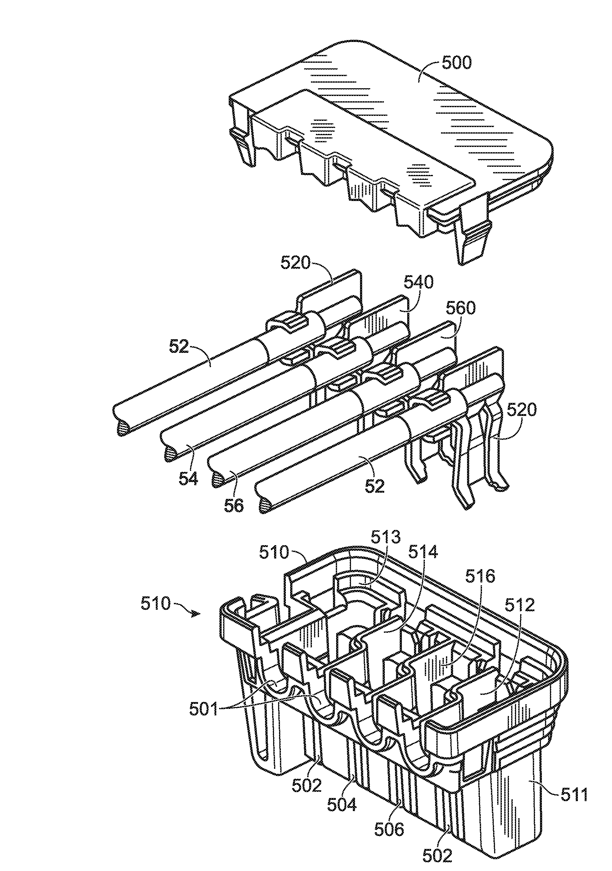
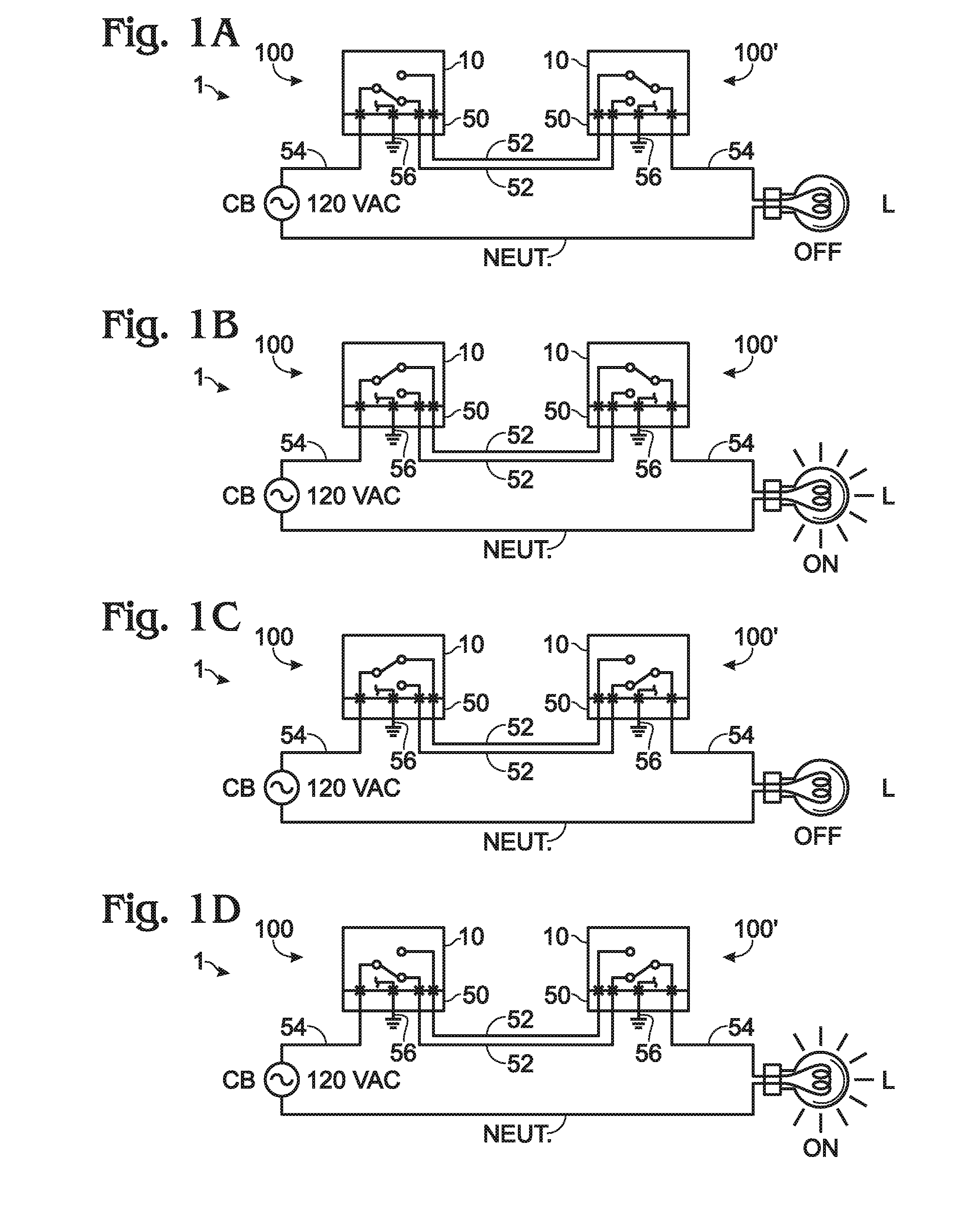
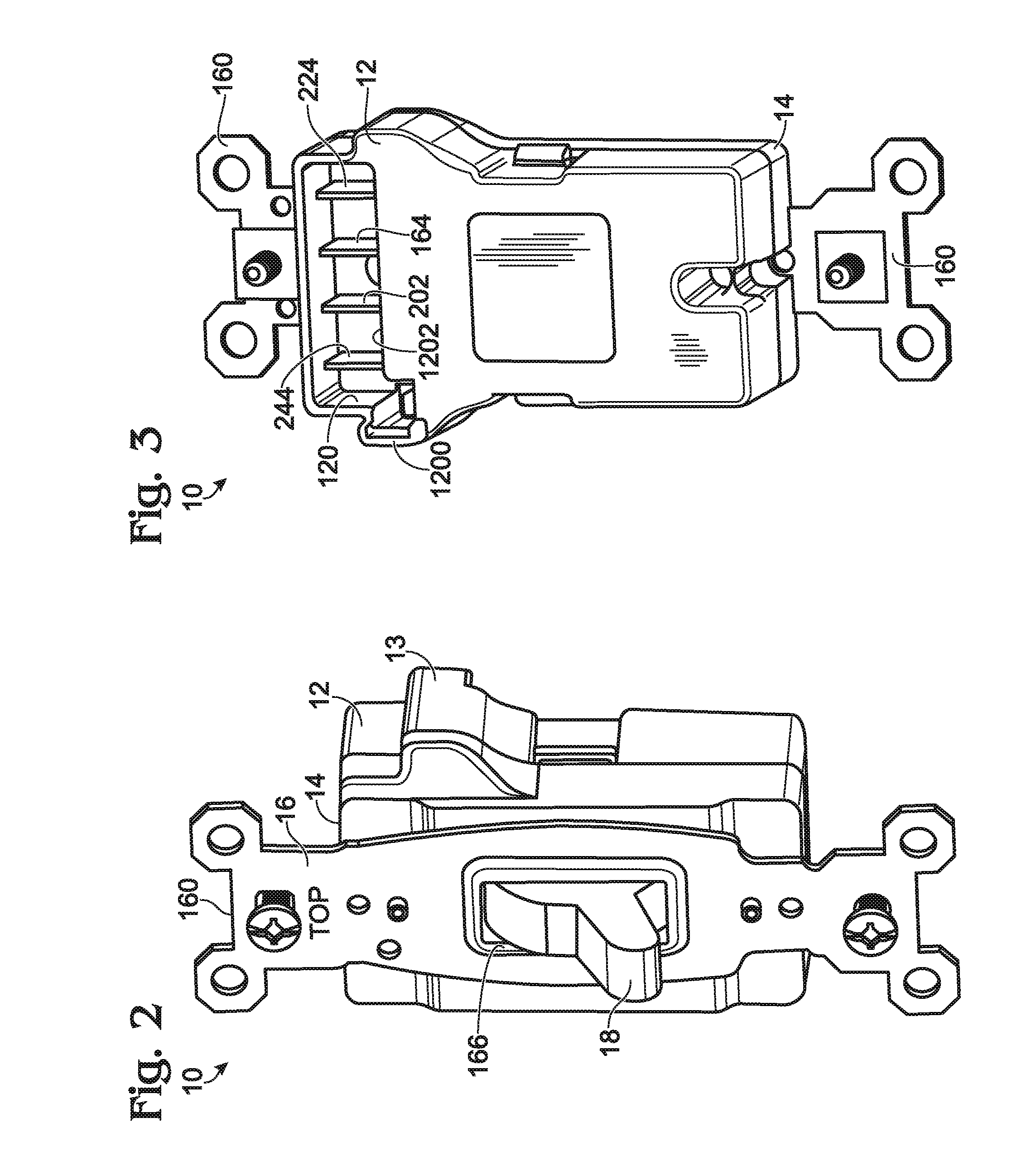
[0040]Reference will now be made in detail to the present exemplary embodiments of the invention, examples of which are illustrated in the accompanying drawings. Wherever possible, the same reference numbers will be used throughout the drawings to refer to the same or like parts. An exemplary embodiment of the system of the present invention is shown in FIG. 1, and is designated generally throughout by reference numeral 100.

[0041]The present invention is directed to an electrical wiring system for use in an AC electrical power distribution circuit that includes one or more AC power conductors disposed between an upstream AC power element and a device box and one or more AC power conductors disposed between the device box and a downstream AC power element. The “upstream” AC power conductors and the “downstream” AC power conductors are routed into an interior portion of the device box and accessible via a front open face of the device box. The upstream AC power element referred to abo...


PUM

PropertyMeasurementUnit
distanceaaaaaaaaaa
AC poweraaaaaaaaaa
AC power distributionaaaaaaaaaa

Abstract

The present invention is directed to an electrical wiring system for use in an AC electrical power distribution circuit including at least one first AC power conductor disposed between an upstream AC power element and a device box and at least one second AC power conductor disposed between the device box and a downstream AC power element. The at least one first AC power conductor and the at least one second AC power conductor are routed into an interior portion of the device box and accessible via a front open face of the device box. The system includes a connector device including a connector housing having a plurality of connector contacts disposed therein.
The plurality of connector contacts are coupled to termination structures configured to couple the at least one first AC power conductor and the at least one second AC power conductor to corresponding contacts of the plurality of connector contacts. An electrical wiring device includes a device housing having a front portion and a rear portion. The front portion includes at least one user-accessible control element disposed thereon. The at least one user-accessible control element is coupled to an electrical switch mechanism disposed in the device housing and coupled to a plurality of device contacts. The plurality of device contacts are accessible by way of a device connection arrangement formed in the rear portion of the device housing. The plurality of device contacts are configured to mate with the plurality of connector contacts when the connector device is coupled to the device connection arrangement.

Description

CROSS-REFERENCE TO RELATED APPLICATIONS[0001]This is a continuation-in-part of U.S. patent application Ser. No. 11 / 531,812 filed on Sep. 14, 2006, which is a continuation-in-part application of U.S. patent application Ser. No. 11 / 274,817 filed on Nov. 15, 2005 and U.S. patent application Ser. No. 11 / 032,420 filed on Jan. 10, 2005, both of which are continuation applications of U.S. patent application Ser. No. 10 / 680,797 filed on Oct. 7, 2003, the contents of which are relied upon and incorporated herein by reference in their entirety, and the benefit of priority under 35 U.S.C. §120 is hereby claimed.BACKGROUND OF THE INVENTION[0002]1. Field of the Invention[0003]The present invention relates generally to electrical circuit installation, and particularly to electrical switching systems with features facilitating rapid and safe installation.[0004]2. Technical Background[0005]Installing electrical circuits in buildings and / or other structures is typically labor intensive, time-consumi...

Claims


Application Information

Patent Timeline
Patent Type & Authority Applications(United States)
IPC IPC(8): H01R13/60H04L69/40
CPCY10T29/4913H01R25/00H01H23/205H02H1/0061H01H23/168H04L29/14H01H1/5866H02H3/162H05K3/30H01R13/7177H01R13/70H04L69/40
Inventor BENOIT, JOHNSAVICKI, JR., GERALD R.WEEKS, RICHARD
Owner PASS SEYMOUR
Why Eureka
Try Eureka