Amputation stabilization device

a stabilization device and amputation technology, applied in the field of amputation stabilization devices, can solve the problems of further medical complications, inability to bear additional loads, and inability to anatomically design tissues to support additional loads

Inactive Publication Date: 2009-08-06
PARSELL DOUGLAS ERIC
View PDF17 Cites 9 Cited by
  • Summary
  • Abstract
  • Description
  • Claims
  • Application Information

AI Technical Summary

Problems solved by technology

Amputation can be used as treatment for physical injury when an extremity is so severely damaged that the extremity's recovery is unlikely and the extremity's continued attachment to the body would cause further medical complications.
However, physical pain is common for these individuals at the anteriodistal bone ends of the amputation when loaded heavily.
Ideally fit prostheses attempt to reduce this pain by redistributing virtually all of the bone end loading to the soft tissues around the calf However, these tissues are not anatomically designed to bear these additional loads.
Thus, other physical problems can result from these loads, such as, for example, soft tissue swelling, loss of bone density, and soft tissue necrosis.

Method used


Image

  • Amputation stabilization device
  • Amputation stabilization device
  • Amputation stabilization device

Examples


Embodiment Construction

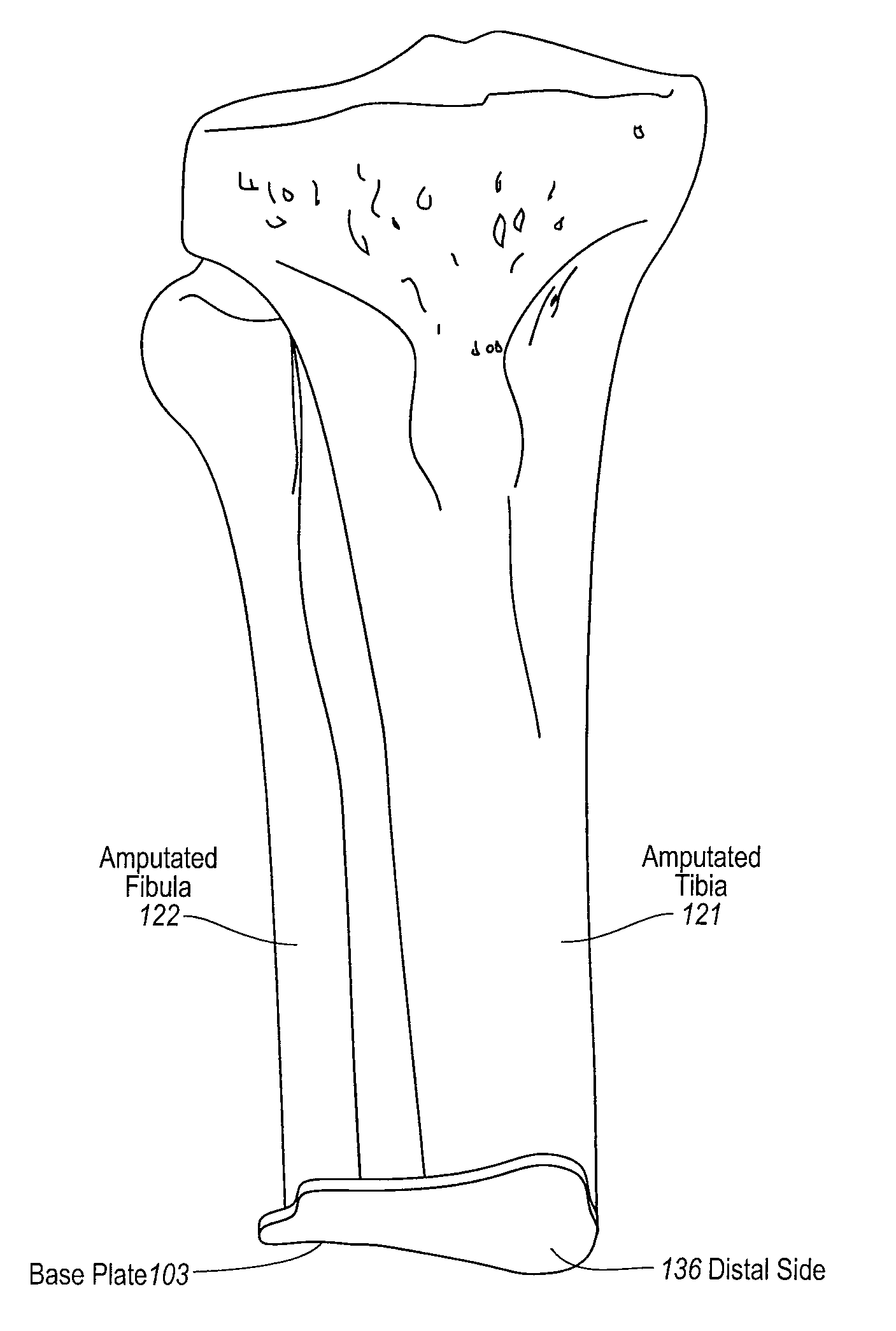
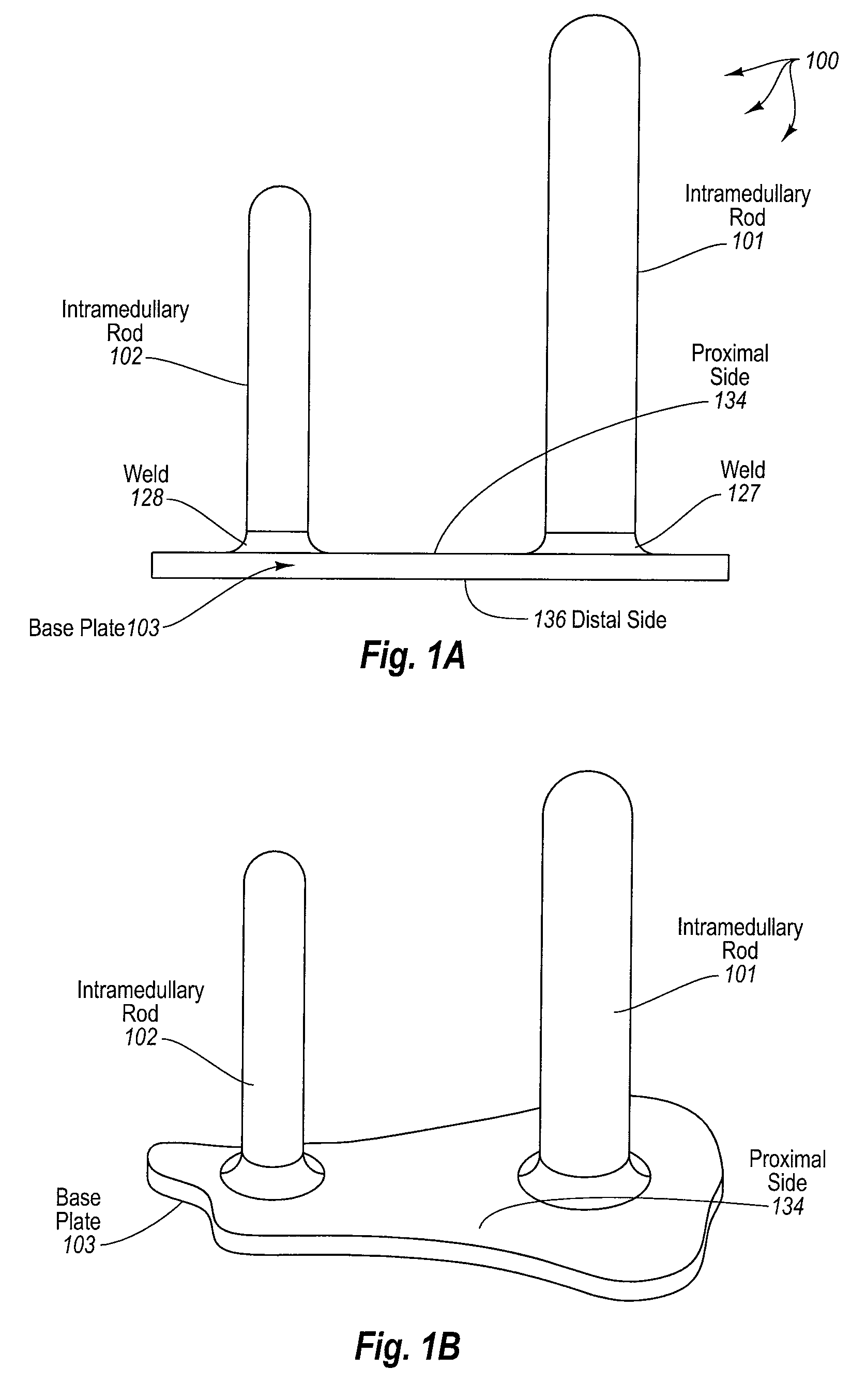
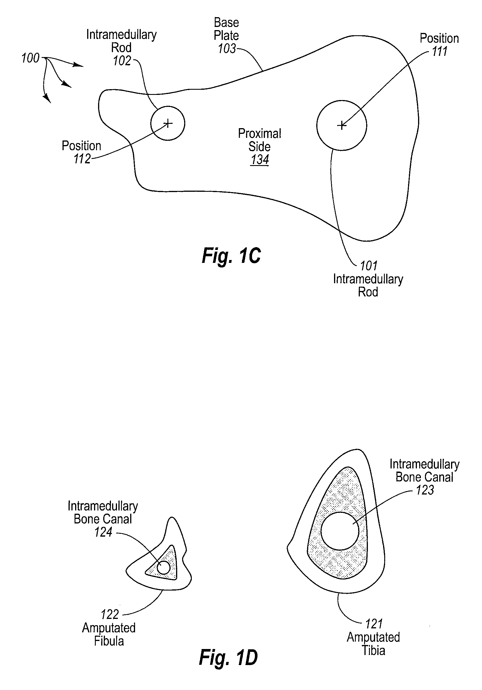
[0029]The present invention extends to an amputation stabilization device. In some embodiments, a dual stemmed amputation implant includes a first intramedullary rod and a second intramedullary rod. The first intramedullary rod is configured for insertion into the distal end of the tibia of an amputated leg. The second intramedullary rod is configured for insertion into the distal end of the tibia of the amputated leg. The dual stem implant also includes a base plate have a proximal side and a distal side.

[0030]The base plate is mechanically connected to the first intramedullary rod and to the second intramedullary rod. The first and second intramedullary rods extend out of the proximal side of the base plate. The position of the mechanical connection of the first intramedullary rod on the base plate relative to the position of mechanical connection of the second intramedullary rod on the base plate is configured to maintain appropriate separation between the tibia and fibula when t...


PUM


Abstract

The present invention extends to a stemmed amputation implant. In some embodiments, a dual stemmed implant includes a base plate and two intramedullary rods extending from the proximal side of the base plate. The two intramedullary rods are configured for insertion into corresponding intramedullary bone canals reamed into remaining portions of amputated bones, such as, for example, a tibia and fibula or an ulna and radius. The position of the intramedullary rods relative to one another is configured to maintain appropriate separation between amputated bones when the first intramedullary rod and the second intramedullary rod are inserted into the amputated bones. In some embodiments, a hollow tube replaces one or more of the intramedullary rods. A hollow tube can be configured to cover the exterior of a bone, such as, for example, the fibula, when the bone is not stable enough for intramedullary fixation.

Description

CROSS-REFERENCE TO RELATED APPLICATIONS[0001]This application claims the benefit of U.S. Provisional Application No. 61 / 063,570, entitled “Dual Stem Amputation Implant”, filed on Feb. 5, 2008, which is incorporated herein in its entirety.BACKGROUND[0002]1. Background and Relevant Art[0003]A human being's loss of a limb or portion thereof is most often an acquired condition resulting from amputation. Amputation of a limb or portion thereof can result from physical injury or can be performed as treatment for a physical injury or disease. Amputation can be used as treatment for physical injury when an extremity is so severely damaged that the extremity's recovery is unlikely and the extremity's continued attachment to the body would cause further medical complications. Amputations can also used to treat a number of diseases, such as, for example, peripheral vascular disease (“PVD”), diabetes, blood clots, and bone infections (e.g., osteomyelitis), when disease prevents proper function ...

Claims


Application Information

Patent Timeline
Patent Type & Authority Applications(United States)
IPC IPC(8): A61F2/28A61B17/56
CPCA61B17/68A61B17/8061A61F2002/30891A61F2/2814A61F2/2846A61B17/809
Inventor PARSELL, DOUGLAS ERIC
Owner PARSELL DOUGLAS ERIC
Why Eureka
Try Eureka