Delamination tool with enhanced force response

Inactive Publication Date: 2009-08-13
LEGOSTAEV JR IVAN
View PDF6 Cites 9 Cited by
  • Summary
  • Abstract
  • Description
  • Claims
  • Application Information

AI Technical Summary

Benefits of technology

[0005]The present invention is directed to a tool for de-laminating two or more bonded material layers wherein two simultaneous force vectors are applied to the tool so as to control the resulting effect of the tool. In particular, the tool is comprised of a handle, a shaft having a proximal and a distal end, a working face, and a strike plate. The handle is connected to the proximal end of the shaft wherein the shaft has a finite length. At the distal end of the shaft is a working face which may be either integral to the shaft or is a separate element which is durably attached to the shaft. At a point on the shaft between the proximal or handle end, and the distal or working face end, a strike plate is durably attached to the shaft. The strike plate is configured to receiving repeated impact by a drive source. Suitable drive sources include, but are not limited to, manually operated discontinuous devices such as weighted head or dead-blow type hammers as well as continuous service devices such as pneumatic and electrically powered impact hammers.
[0006]In practical application, an operator applies at least one force vector (FV1) by grasping the handle of the present invention and directing the coinciding work face against a su

Problems solved by technology

Due to the obtuse angle employed in directing the impact tool against the surface, particularly when a shallow depth between bonded pieces to be separated is desired, it can become problematic for the operator to maintain precise and continuous control over the depth which the impact tool is driven.
This decrease in height of the distal end of the impact tool becomes problematic in the operator being able to apply sufficient impact force, especially imparting that impact force without risk of deleterious impact of the drive force on the surface itself versus th

Method used


Image

  • Delamination tool with enhanced force response
  • Delamination tool with enhanced force response
  • Delamination tool with enhanced force response

Examples


Embodiment Construction

[0025]While the present invention is susceptible of embodiment in various forms, there is shown in the drawings and will hereinafter be described a presently preferred embodiment of the invention, with the understanding that the present disclosure is to be considered as an exemplification of the invention, and is not intended to limit the invention to the specific embodiment illustrated.

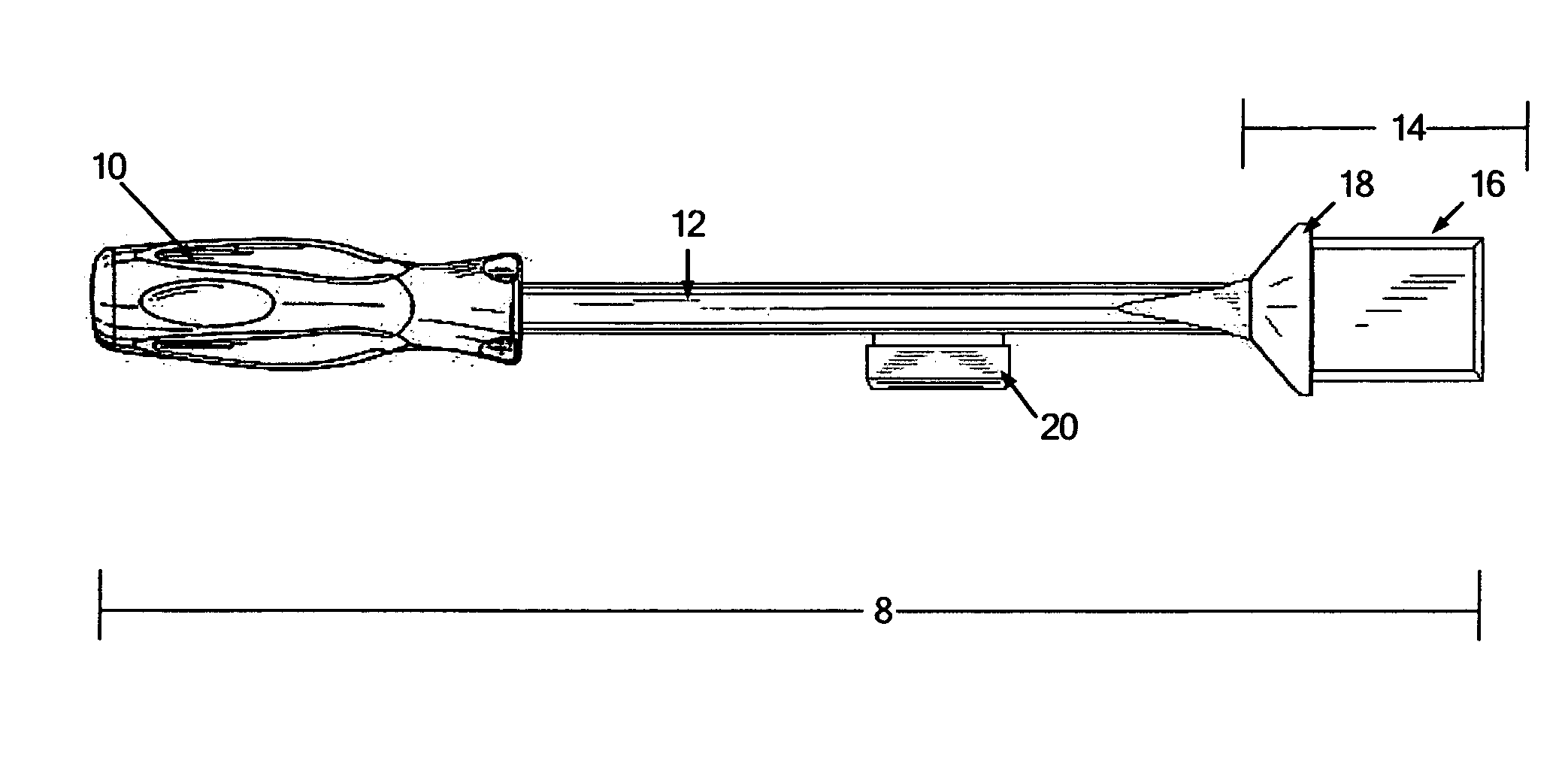
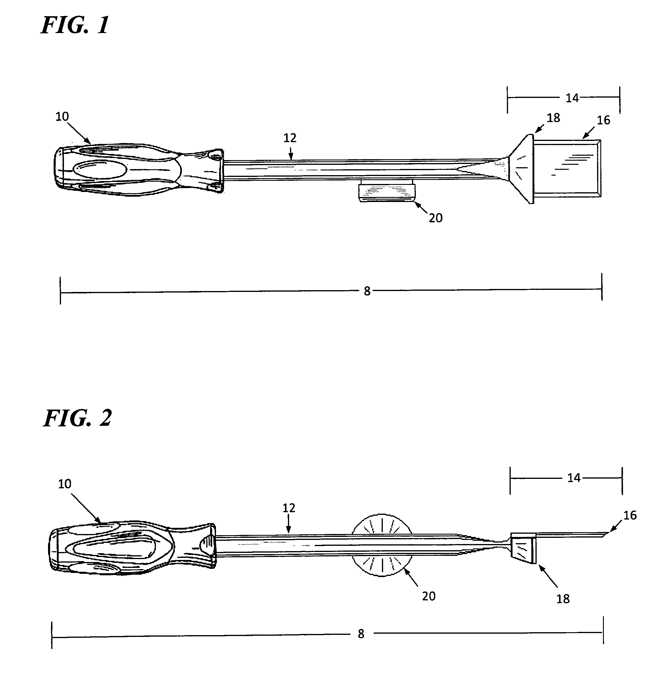
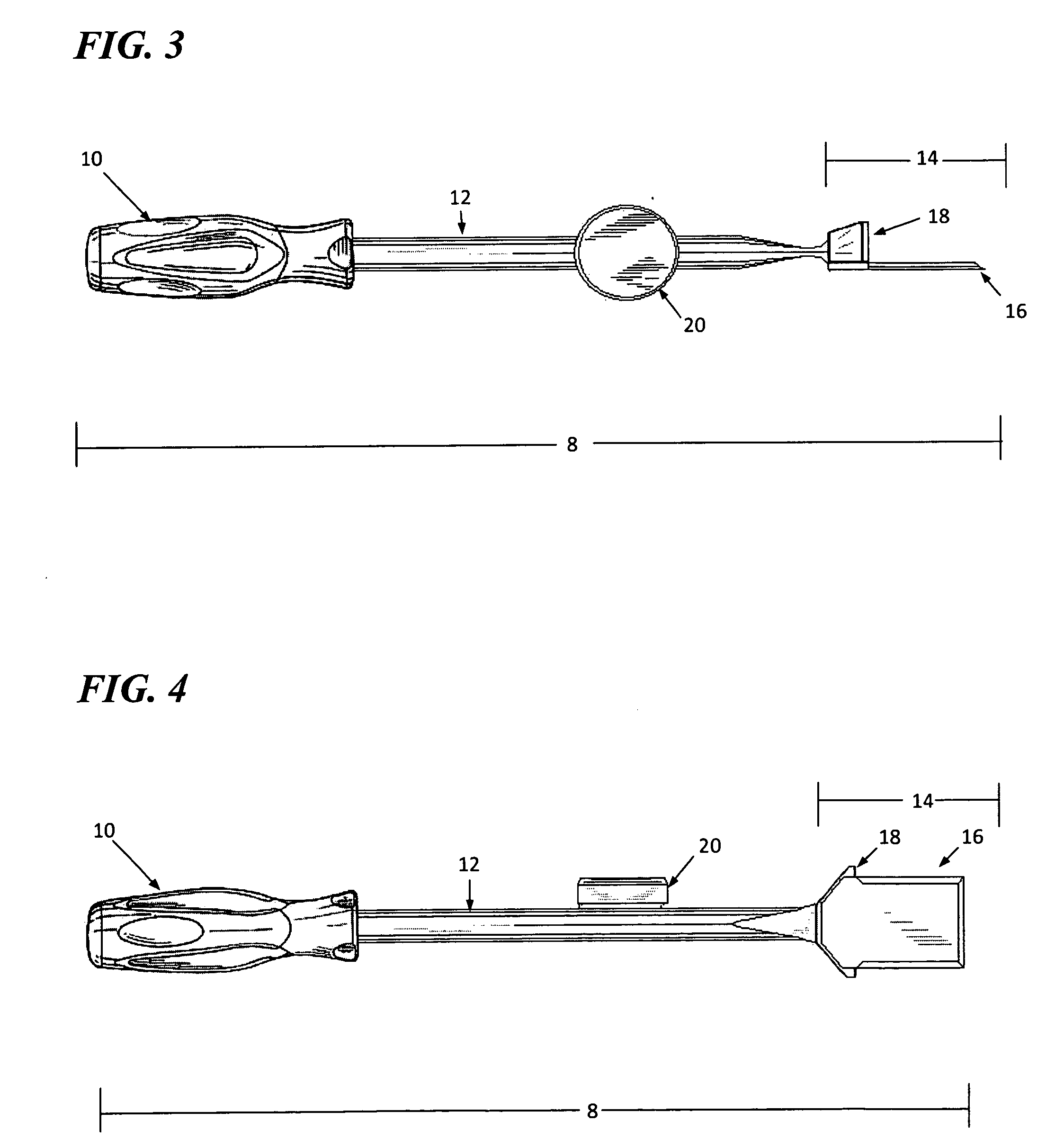
[0026]The present invention is directed to a tool for modifying or interacting with a surface wherein two simultaneous force vectors are applied to the tool so as to control the resulting effect of the tool. As depicted in FIGS. 1 through 14, and specifically in FIG. 1, impact tool 8 is generally comprised of a handle 10, a shaft having a proximal and a distal end 12, a working face 14, a blade element 16 and a strike plate 20.

[0027]Handle 10 is connected to the proximal end of shaft 12 wherein the shaft has a finite length. Preferably, shaft 12 is between 6 and 18 inches in length, though specialize...


PUM

PropertyMeasurementUnit
Fractionaaaaaaaaaa
Lengthaaaaaaaaaa
Lengthaaaaaaaaaa

Abstract

The present invention is directed to a tool for de-laminating two or more bonded material layers wherein two simultaneous force vectors are applied to the tool so as to control the resulting effect of the tool. In particular, the tool is comprised of a handle, a shaft having a proximal and a distal end, a working face, and a strike plate. The handle is connected to the proximal end of the shaft wherein the shaft has a finite length. At the distal end of the shaft is a working face which may be either integral to the shaft or is a separate element which is durably attached to the shaft. At a point on the shaft between the proximal or handle end, and the distal or working face end, a strike plate is durably attached to the shaft. The strike plate is configured to receiving repeated impact by a drive source.

Description

BACKGROUND[0001]Impact tools are of particular importance in affecting a surface that requires treatment or modification. Chisels, scrapers, blades, and gouges are common examples of impact tools which are used to remove layers of material, de-scale surface, de-laminate bonded layers and the like. In general application these kinds and types of impact tools are used at an obtuse angle to the surface to be treated, wherein a working face is in direct contact with the surface, and a drive force is applied to the distal end of the impact tool through repeated blows by a weighted mass. Due to the obtuse angle employed in directing the impact tool against the surface, particularly when a shallow depth between bonded pieces to be separated is desired, it can become problematic for the operator to maintain precise and continuous control over the depth which the impact tool is driven. Further, as the obtuse angle increases in order to achieve a shallow treatment depth, the distance between ...

Claims


Application Information

Patent Timeline
IPC IPC(8): B32B37/00
CPCB25D3/00Y10T156/1967Y10T156/1184
Inventor LEGOSTAEV, JR., IVAN
Owner LEGOSTAEV JR IVAN
Why Eureka
Try Eureka