
Subsoil automatic rotary drilling system for drilling oil, mineral and water wells

a technology of automatic rotary drilling and oil wells, which is applied in the direction of drilling machines and methods, fluid removal, construction, etc., can solve the problems of affecting the well productivity and operating safety of the well, and a lot of drawbacks

Inactive Publication Date: 2009-08-13
BAGASSI WALTER
View PDF9 Cites 15 Cited by
  • Summary
  • Abstract
  • Description
  • Claims
  • Application Information

AI Technical Summary

Benefits of technology

[0006]Thus, the aim of the invention is to eliminate the above mentioned drawbacks, as well as yet other drawbacks, of prior mechanical well drilling systems including several drilling mechanical pieces and equipments arranged in a loose and separated condition through the overall drilling yard area.
[0007]Within the above mentioned aim, a main object of the present invention is to provide a fully automatic drilling system, for the above mentioned applications, in which, in particular, the handling of the pipe elements designed for forming the well casing or liner pipe string is performed in a fully automatic, substantially non mechanical, manner, thereby improving the productivity, profitability and safety of the producing well.
[0008]Another important object of the invention is to provide such an automatic drilling system reuniting, on a single drilling system substructure, either of a fixed or skidding type, a complete arrangement of mechanical, hydraulic, electric and electronic equipments, and also including a novel drilling derrick supporting a driving head which is vertically bidirectionally driven by a plurality of driving hydraulic cylinders operating preferably in a pulling mode of operating, thereby overcoming any combined bending and compressive stress problems.

Problems solved by technology

The above mentioned prior pipe handling mechanical systems, however, have a lot of drawbacks negatively affecting the well productivity and operating safety.

Method used


Image

  • Subsoil automatic rotary drilling system for drilling oil, mineral and water wells
  • Subsoil automatic rotary drilling system for drilling oil, mineral and water wells

Examples


Embodiment Construction

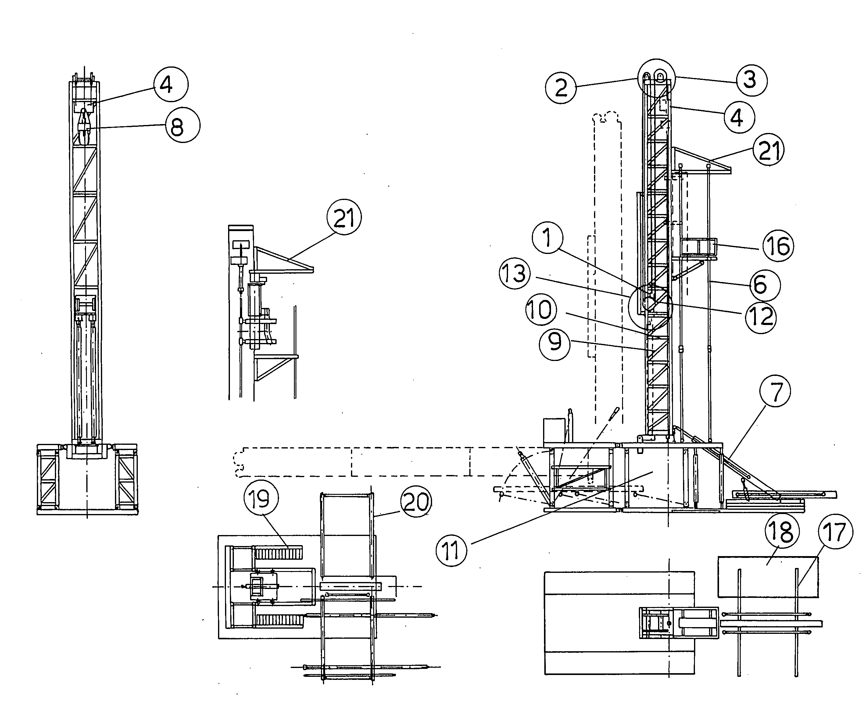
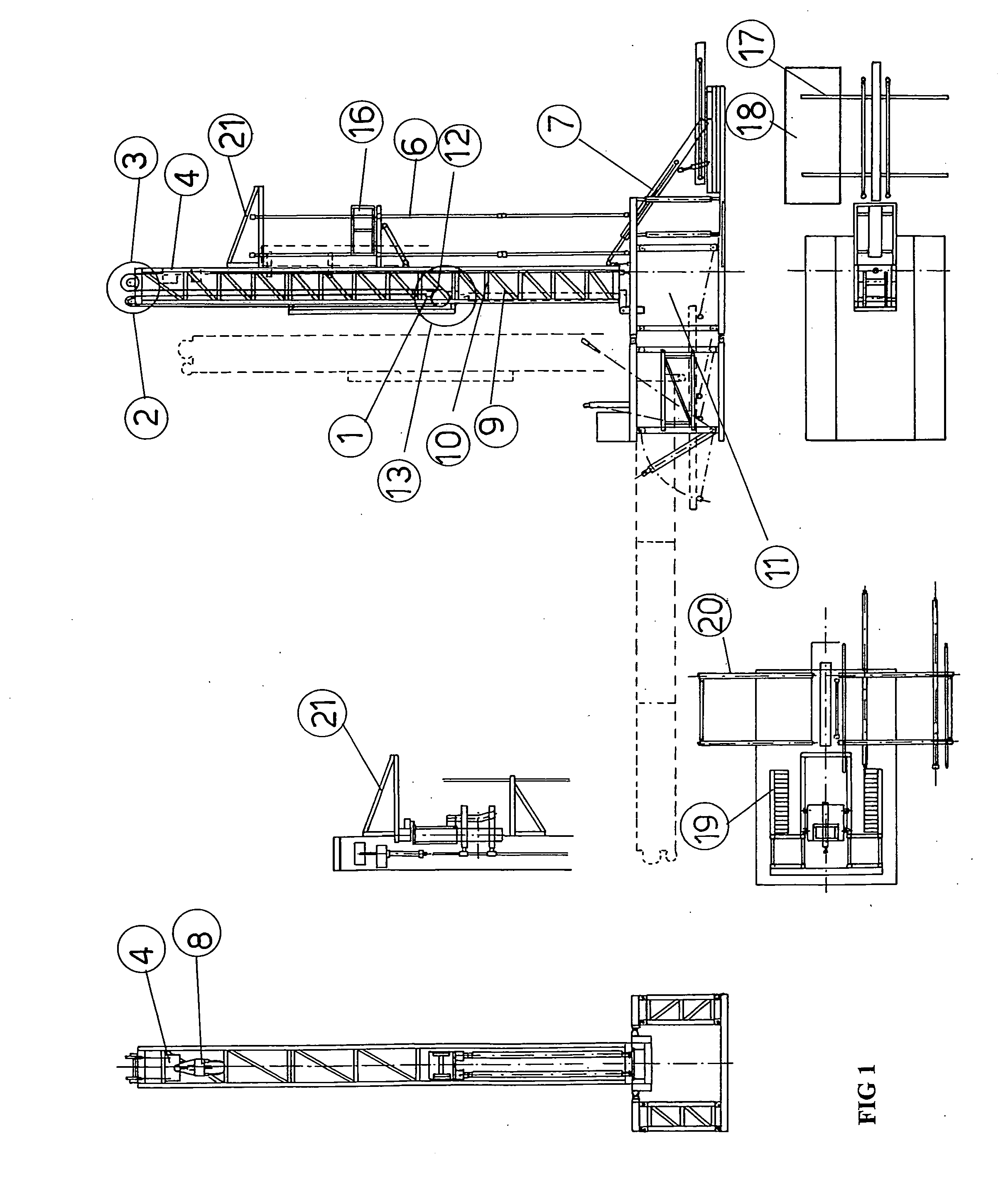
[0014]With reference to the drawing, the inventive well drilling system or yard comprises, on a single substructure, the following main component elements: substructure means 11, including two parallelogram frames adapted to support the overall weight of the drilling system; a derrick fixed construction 10 with a fixed tackle 3 and a rotary driving head 8, a loader 7 for loading pipe elements 6 as necessary for providing the drilling pipe string for encasing or lining the wellbore being drilled.

[0015]The system further comprises a plurality of cables each having a dead end 1, as well as pulling and pushing cylinders 9, a first transmission pulley 2, a second transmission pulley 2 and a third transmission pulley 3.

[0016]More specifically, the inventive drilling system, which is exclusively applied to an automatic well rotary drilling system or yard, comprises a lot of operating components all of which are assembled on a single fixed or movable substructure. Thus, on this substructure...


PUM


Abstract

A subsoil automatic rotary drilling system for drilling oil, mineral and water wells, characterized in that said system comprises, on a single system substructure, at least a triple-transmission hydraulic arrangement for lowering and raising a plurality of pipe elements to be introduced into and removed from a wellbore, said arrangement including a plurality of operating cables, each said cable having a dead end fixed to a cylinder carriage also supporting a plurality of transmission pulleys to handle together, while providing a triple stroke of pulling and pushing cylinders, two, three, four drilling pipe elements, having each a length of about 9.20 m (range 2).

Description

BACKGROUND OF THE INVENTION[0001]The present invention relates to a subsoil automatic rotary drilling system for drilling oil, mineral and water wells.[0002]More specifically, the invention relates to such an automatic drilling system including a driving head and a lifting tackle, both driven by hydraulic cylinders having an operating cylinder stroke adapted to operatively drive three range-2 rods, with related container and loader means for the material necessary to properly perform the drilling operations.[0003]As is known, onshore drilling operations and, in particular, the operations for installing and removing into / from the wellbore being made the series of pipes provided for forming the pipe string for forming the wellbore casing or lining, are conventionally performed, in a dedicated drilling yard including a respective drilling derrick, by dedicated systems which are generally of a mechanical arrangement.[0004]The above mentioned prior pipe handling mechanical systems, howev...

Claims


Application Information

Patent Timeline
IPC IPC(8): E21B19/00E21B19/20E21B19/02E21B19/08E21B7/00
CPCE21B19/084
Inventor BAGASSI, WALTER
Owner BAGASSI WALTER
Learn More