
Weld signature monitoring method and apparatus

a monitoring method and signature technology, applied in the direction of instruments, manufacturing tools, structural/machine measurement, etc., can solve the problems of less than optimal algorithmically comparing the various individual welding system variables to stored thresholds, and the difficulty of process

Inactive Publication Date: 2009-08-13
GM GLOBAL TECH OPERATIONS LLC
View PDF4 Cites 164 Cited by
  • Summary
  • Abstract
  • Description
  • Claims
  • Application Information

AI Technical Summary

Benefits of technology

[0013]In another aspect of the invention, an apparatus is provided for monitoring a weld signature during a welding process to thereby predict a quality of a welding joint. The apparatus includes a welding gun operable for forming a weld joint, a power supply configured for supplying a welding voltage and a welding current for selectively powering the welding gun, and a sensor for detecting value

Problems solved by technology

However, monitoring the welding process in real time in order to accurately detect an acceptable, “passing”, or a “good” weld can be a challenging process due to the substantial number of different welding system and environmental operating variables that interrelate in a complex manner to influence the resultant weld quality.
Algorithmically comparing the various individual welding system variables to stored thresholds can also be less than optimal due to the difficulty in precisely determining an isolated or individual contribution or effect of variance in a particular variable value on the overall quality of a resultant weld joint.

Method used


Image

  • Weld signature monitoring method and apparatus
  • Weld signature monitoring method and apparatus
  • Weld signature monitoring method and apparatus

Examples


Embodiment Construction

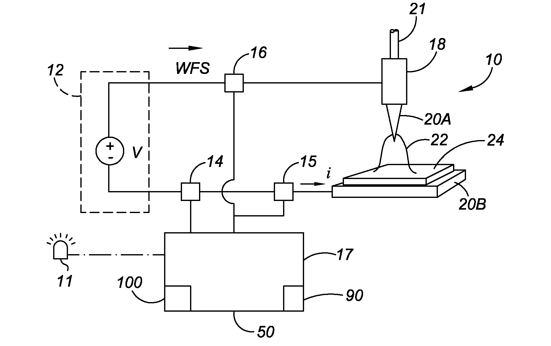
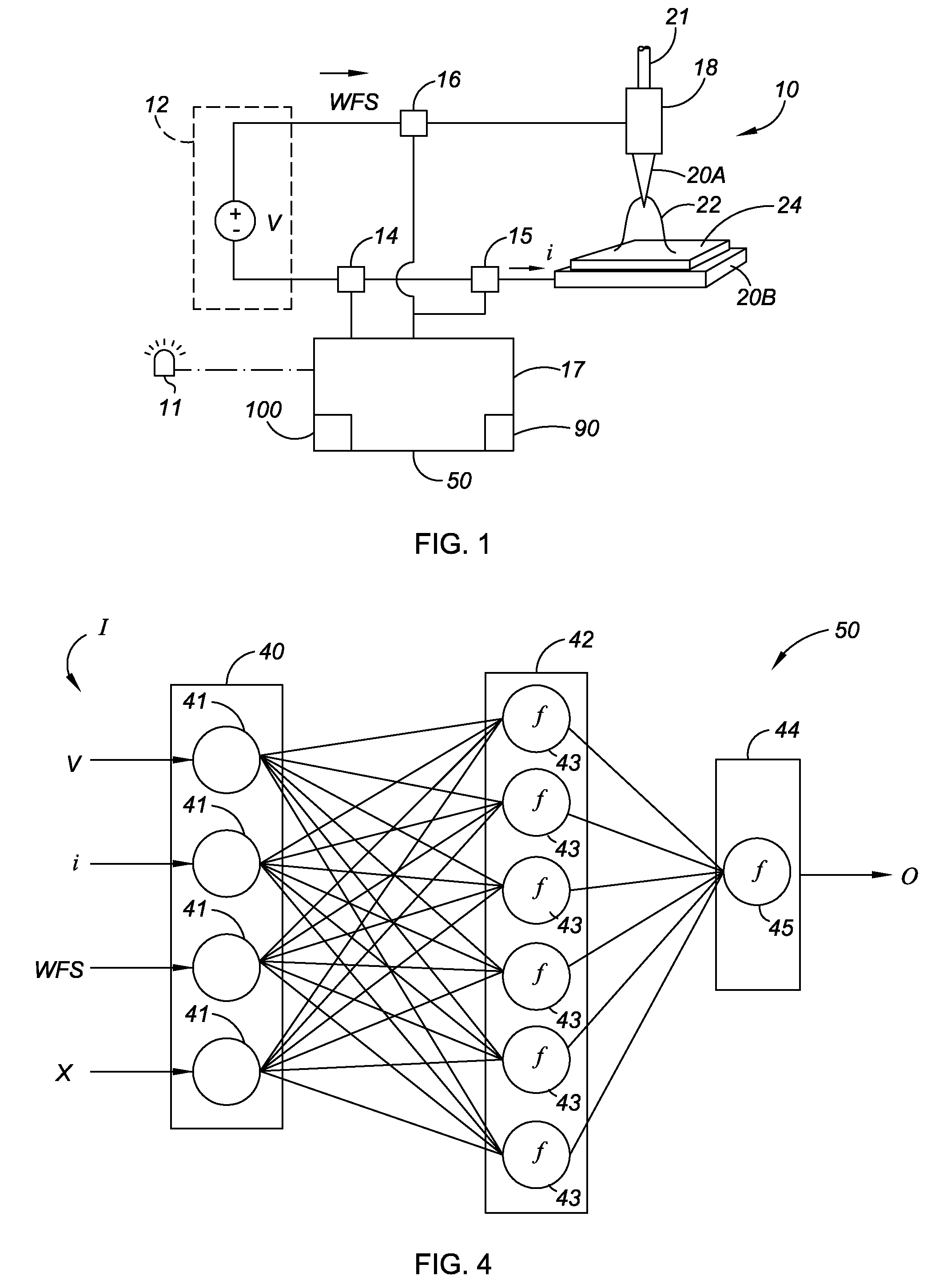
[0020]Referring to the drawings, wherein like reference numbers correspond to like or similar components throughout the several figures, and beginning with FIG. 1, an apparatus and method for monitoring a weld signature of a welding process is provided herein, which may be used in a variety of different welding processes, including but not limited to single work piece operations, joining two or more work pieces or surfaces together, and / or for joining two ends of a single work piece together. Accordingly, a welding apparatus 10 includes an automated or manual welding device or welding gun 18, which is operatively connected to an integrated control unit or controller 17 and a power supply 12 providing a voltage, represented in FIG. 1 as the variable “V”. A plurality of sensors 14, 15, and 16, which may alternately be configured as a single sensor and / or housed together in a common sensor housing (not shown), are adapted for sensing, measuring, detecting, and / or otherwise determining ...


PUM

PropertyMeasurementUnit
Compositionaaaaaaaaaa
Speedaaaaaaaaaa
Electric potential / voltageaaaaaaaaaa

Abstract

A method monitors a weld signature of a welding apparatus by processing the signature through a neural network to recognize a pattern, and by classifying the weld signature in response to the pattern. The method determines if the weld signature is sufficiently different from training weld signatures stored in a database, and records the weld signature in the database when sufficiently different. The method tests a weld joint to determine values of different weld joint properties, and then correlates the signature with the weld data to validate the database. An apparatus monitors a weld signature during a welding process to predict welding joint quality, and includes a welding gun, a power supply, and a sensor for detecting welding voltage, current, and wire feed speed (WFS). A neural network receives the welding process values and classifies the signature into different weld classifications each corresponding to a predicted welding joint quality.

Description

TECHNICAL FIELD[0001]The invention relates generally to a method and apparatus for monitoring a weld signature during a welding process by classifying the weld signature using a neural network model or a neural processor.BACKGROUND OF THE INVENTION[0002]Welding systems are utilized extensively in various manufacturing processes to join or bond various work surfaces. Arc welding systems in particular may be used to strongly fuse or merge separate work surfaces into a unified body via the controlled application of intense heat and an intermediate material to form a resultant weld joint. A strong metallurgical bond forms when the intermediate material, which is quickly rendered molten in the presence of a high temperature arc during the arc welding process, ultimately cools and solidifies. Ideally, the resultant weld joint has approximately the same overall strength and other material properties as the originally separate work surfaces.[0003]In an arc welding process, the arc may be fo...

Claims


Application Information

Patent Timeline
IPC IPC(8): B23K9/095G01M19/00G01M99/00
CPCB23K9/0953G06N3/02B23K9/10
Inventor HAMPTON, JAY
Owner GM GLOBAL TECH OPERATIONS LLC
Learn More