Echoing ultrasound atomization and mixing system

Inactive Publication Date: 2009-08-13
BACOUSTICS LLC
View PDF11 Cites 18 Cited by
  • Summary
  • Abstract
  • Description
  • Claims
  • Application Information

AI Technical Summary

Benefits of technology

[0014]The amount of mixing occurring within the internal chamber may be controlled by adjusting, the amplitude of the ultrasonic vibrations traveling down the length of the horn. Increasing the amplitude of the ultrasonic vibrations increases the degree to which the fluids within the chamber are agitated and/or cavitated. If the horn is ultrasonically vibrated in resonance by a piezoelectric transducer driven by an electrical signal supplied by a generator, then increasing the voltage of the electrical signal will increase the amplitude of the ultrasonic vibrations traveling down the horn.
[0015]As with typical pressure driven fluid atomizers, the ultrasound atomization apparatus utilizes pressure changes within the fluid to create the kinetic energy that drives atomization. Unfortunately, pressure driven fluid atomization can be adversely impacted by changes in environmental conditions. Most notably, a change in the pressure of the environment into which the atomized fluid is to be sprayed may decrease the level of atomization and/or distort the spray pattern. As a fluid passes through a pressure driven fluid atomizer, it is pushed backwards by the pressure of the environment. Thus, the net pressure acting on the fluid is the difference of the pressure pushing the fluid through the atomizer and the pressure of the environment. It is the net pressure of the fluid that is converted to kinetic e

Problems solved by technology

This can be inefficient and/or result in unequal mixing.
However, mixing of the fluids is hindered by the simultaneous atomization of the fluids.
Though capable of atomizing and mixing liquids with ultrasonic vibrations emanating from their distal surfaces, these devices have not b

Method used


Image

  • Echoing ultrasound atomization and mixing system
  • Echoing ultrasound atomization and mixing system
  • Echoing ultrasound atomization and mixing system

Examples


Example

[0025]Preferred embodiments of the ultrasound atomization and / or mixing apparatus are illustrated throughout the figures and described in detail below. Those skilled in the art will immediately understand the advantages for mixing and / or atomizing material provided by the atomization and / or mixing apparatus upon review.

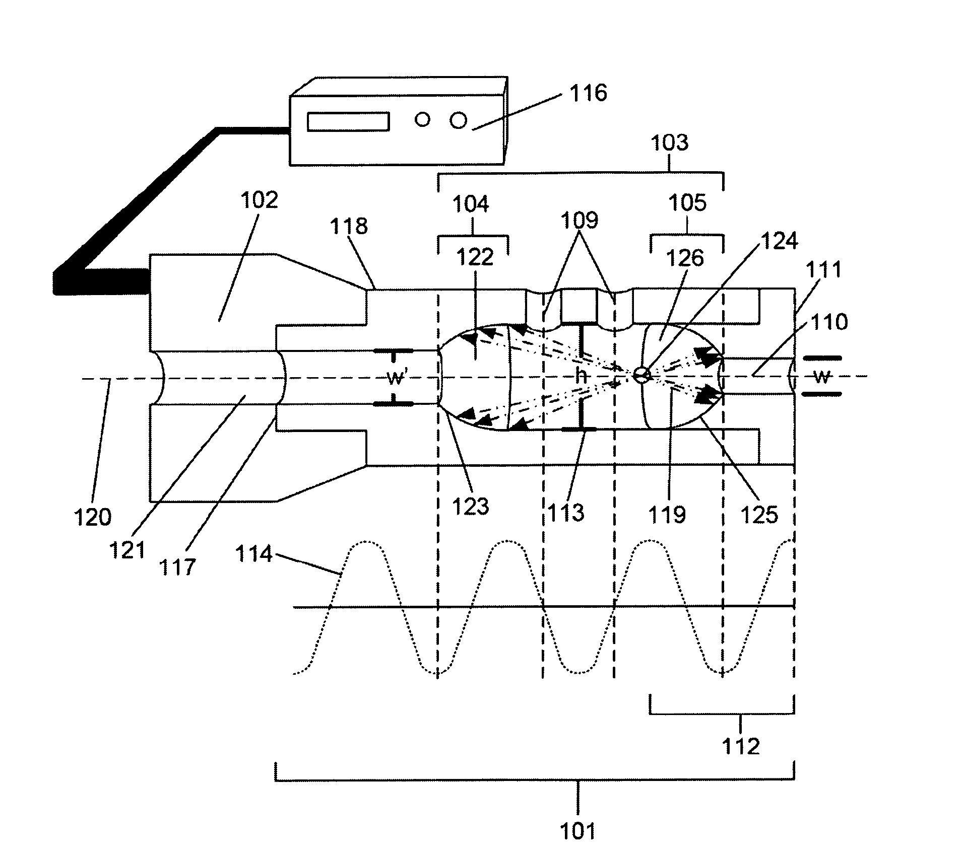
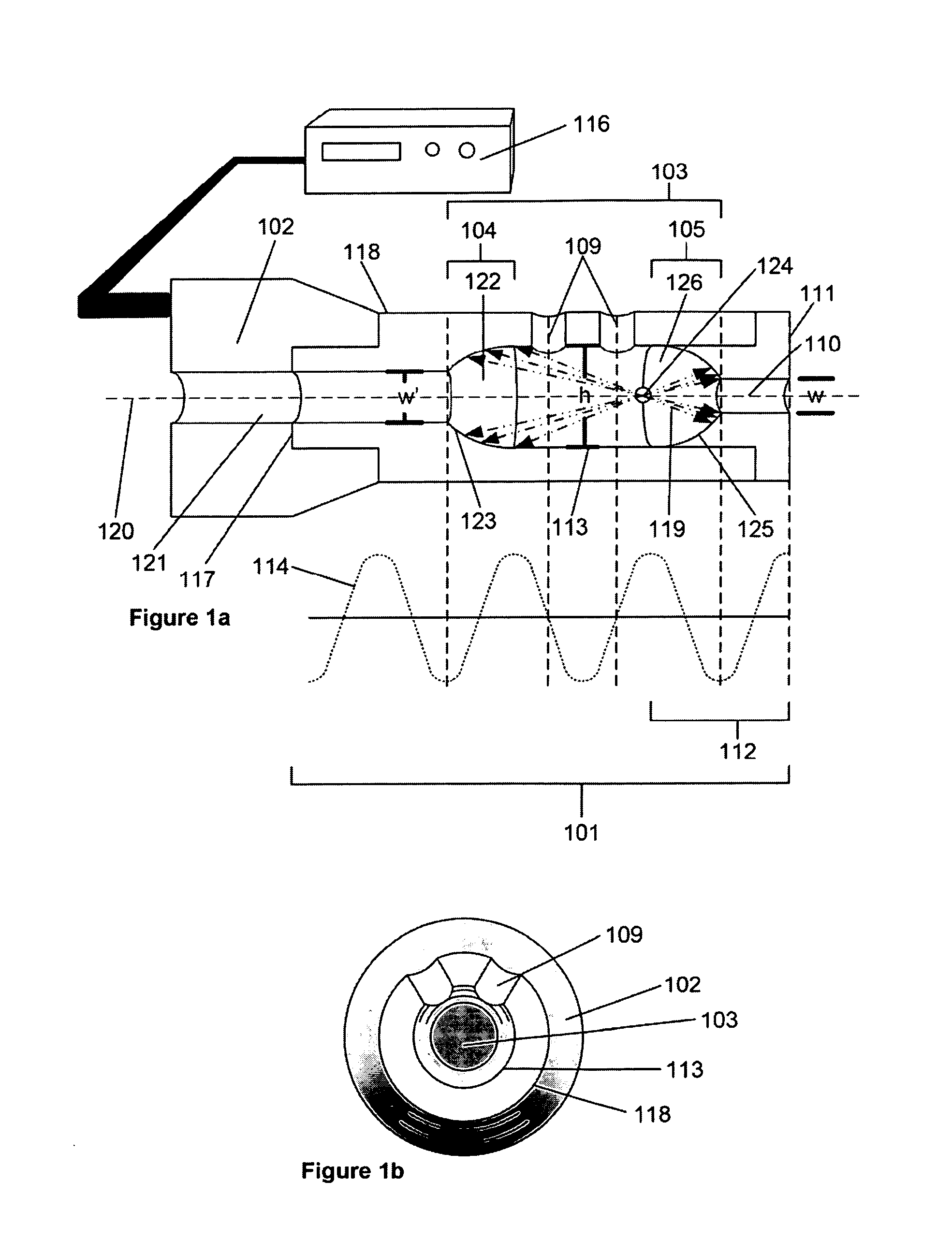
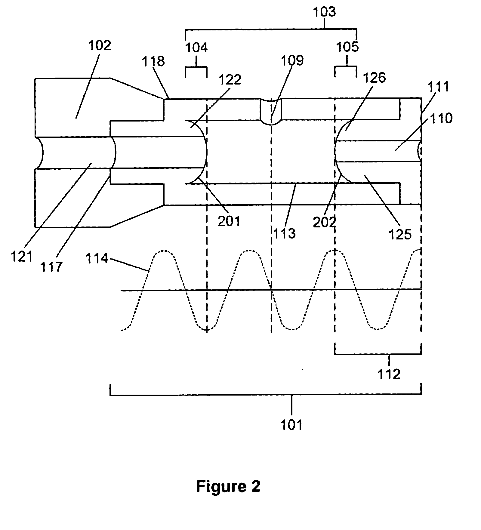
[0026]FIGS. 1a and 1b illustrate an embodiment of the ultrasound atomization and / or mixing apparatus comprising a horn 101 and an ultrasound transducer 102 attached to the proximal surface 117 of horn 101 powered by generator 116. As ultrasound transducers and generators are well known in the art they need not be described in detail herein. Ultrasound horn 101 comprises a proximal surface 117, a radiation surface 111 opposite proximal surface 117, and at least one radial surface 118 extending between proximal surface 117 and radiation surface 111. Within horn 101 is an internal chamber 103 containing a back wall 104, a front wall 105, at least one side wall 113 extend...


PUM


Abstract

An ultrasound apparatus capable of mixing and/or atomizing fluids is disclosed. The apparatus includes a horn having an internal chamber through which fluids to be atomized and/or mixed flow. Connected to the horn's proximal end, a transducer powered by a generator induces ultrasonic vibrations within the horn. Traveling down the horn from the transducer, the ultrasonic vibrations induce the release of ultrasonic energy into the fluids to be atomized and/or mixed as they travel through the horn's internal chamber. As the ultrasonic vibrations travel through the chamber, the fluids within the chamber are agitated and/or begin to cavitate, thereby mixing the fluids. Upon reaching the front wall of the chamber, the ultrasonic vibrations are reflected back into the chamber, like an echo. The ultrasonic vibrations echoing off the front wall pass through the fluids within the chamber a second time, further mixing the fluids.

Description

BACKGROUND OF THE INVENTION[0001]The present invention relates to an apparatus utilizing ultrasonic waves traveling through a horn and / or resonant structure to atomize, assist in the atomization of, and / or mix fluids passing through the horn and / or resonant structure.[0002]Liquid atomization is a process by which a liquid is separated into small droplets by some force acting on the liquid, such as ultrasound. Exposing a liquid to ultrasound creates vibrations and / or cavitations within the liquid that break it apart into small droplets. U.S. Pat. No. 4,153,201 to Berger et al., U.S. Pat. No. 4,655,393 to Berger, and U.S. Pat. No. 5,516,043 to Manna et al. describe examples of atomization systems utilizing ultrasound to atomize a liquid. These devices possess a tip vibrated by ultrasonic waves passing through the tip. Within the tips are central passages that carry the liquid to be atomized. The liquid within the central passage is driven towards the end of the tip by some force actin...

Claims


Application Information

Patent Timeline
IPC IPC(8): B05B3/14
CPCB01F11/0258B05B17/063B05B17/0623B05B7/0408Y10T137/2191Y10T137/0391B01F31/85
Inventor BABAEV, EILAZ
Owner BACOUSTICS LLC
Why Eureka
Try Eureka