
Mass Transfer Device

Inactive Publication Date: 2009-08-13
MALETA BOGDAN VLADIMIROVICH +1
View PDF11 Cites 22 Cited by
  • Summary
  • Abstract
  • Description
  • Claims
  • Application Information

AI Technical Summary

Benefits of technology

[0006]The primary aim of the present invention is the improvement of known mass exchange contact devices, namely: an extension of the steam load operating range, reduction of the metal content (amount of metal consumed for making the device), the height, and costs of the device, increasing the reliability and durability of device operation. Other aims of the invention may become apparent to a skilled artisan upon learning the present disclosure.
[0009]1) The invented device has a technological advantage of the valve-tray stationary process, namely: reducing the free cross-section of the barbotage unit with decreasing steam expenditure. This allows maintaining a substantially constant pressure difference on the tray that causes the double-acting valve to be in the upper position.
[0011]3) The reduction of the height of device by 30% can be achieved in the proposed design that allows reducing the column's metal content by 10% resulting in significant cutting its cost.
[0012]4) During a smooth shutting the steam flow, the valve moving downward decelerates at the level of orifices on the sidewalls of the barbotage unit, and mildly and strikelessly lowers on the descending limiter, which prolongs the service life of the device.

Problems solved by technology

A disadvantage of the above-described device is that the barbotage unit has a fixed free cross-section that causes a shift of the operation range to the side of increased steam expenditure under insubstantial liquid loads.
Another disadvantage is its excessive height (the distance between the main and additional trays) that leads to an increase of the column's height and its metal content that involves additional costs.

Method used


Image

  • Mass Transfer Device
  • Mass Transfer Device
  • Mass Transfer Device

Examples


Embodiment Construction

[0018]While the invention may be susceptible to embodiment in different forms, there are described in detail herein below, specific embodiments of the present invention, with the understanding that the present disclosure is to be considered an exemplification of the principles of the invention, and is not intended to limit the invention to that as illustrated and described herein.

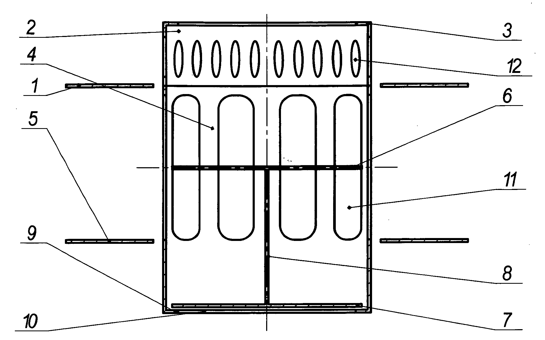
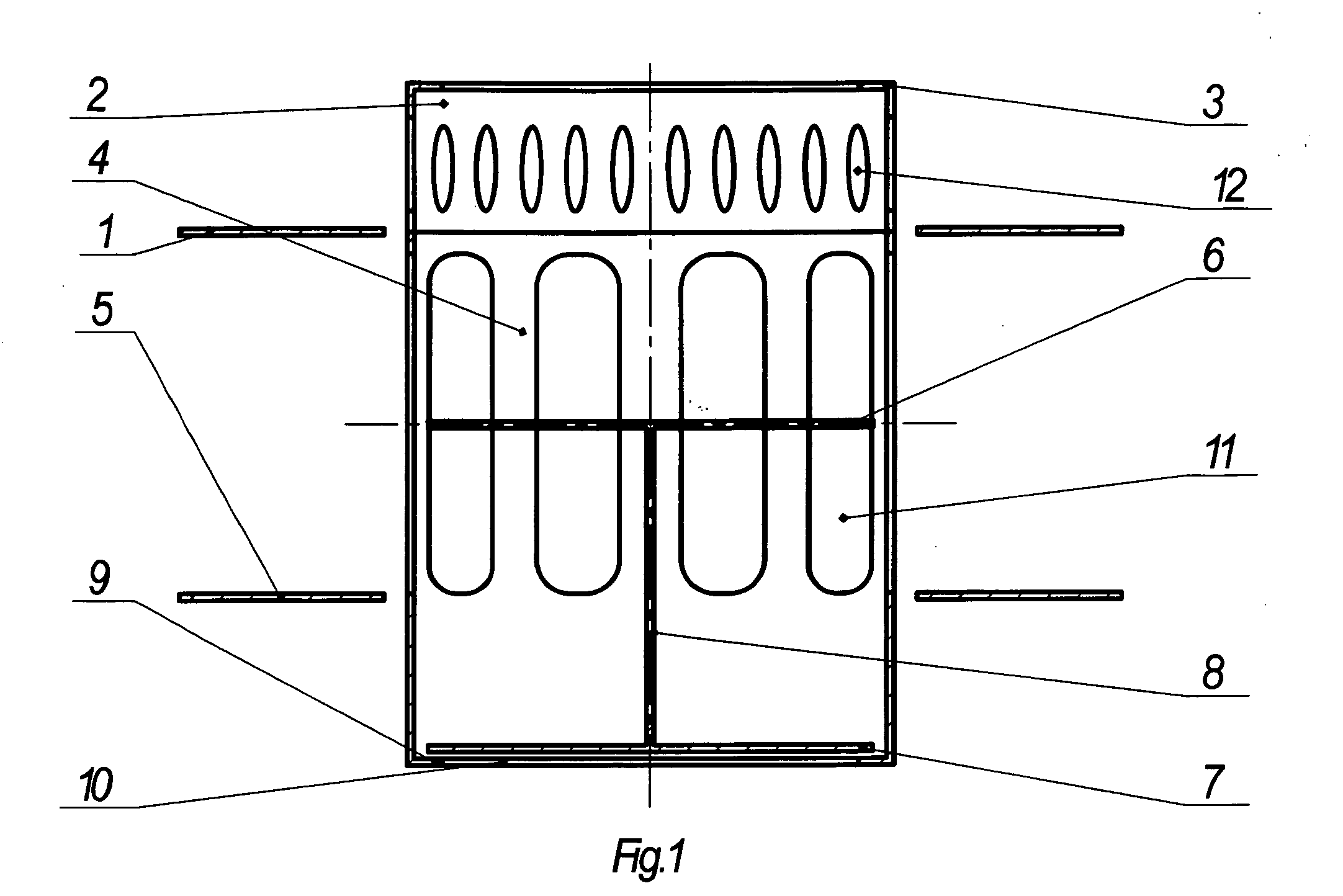
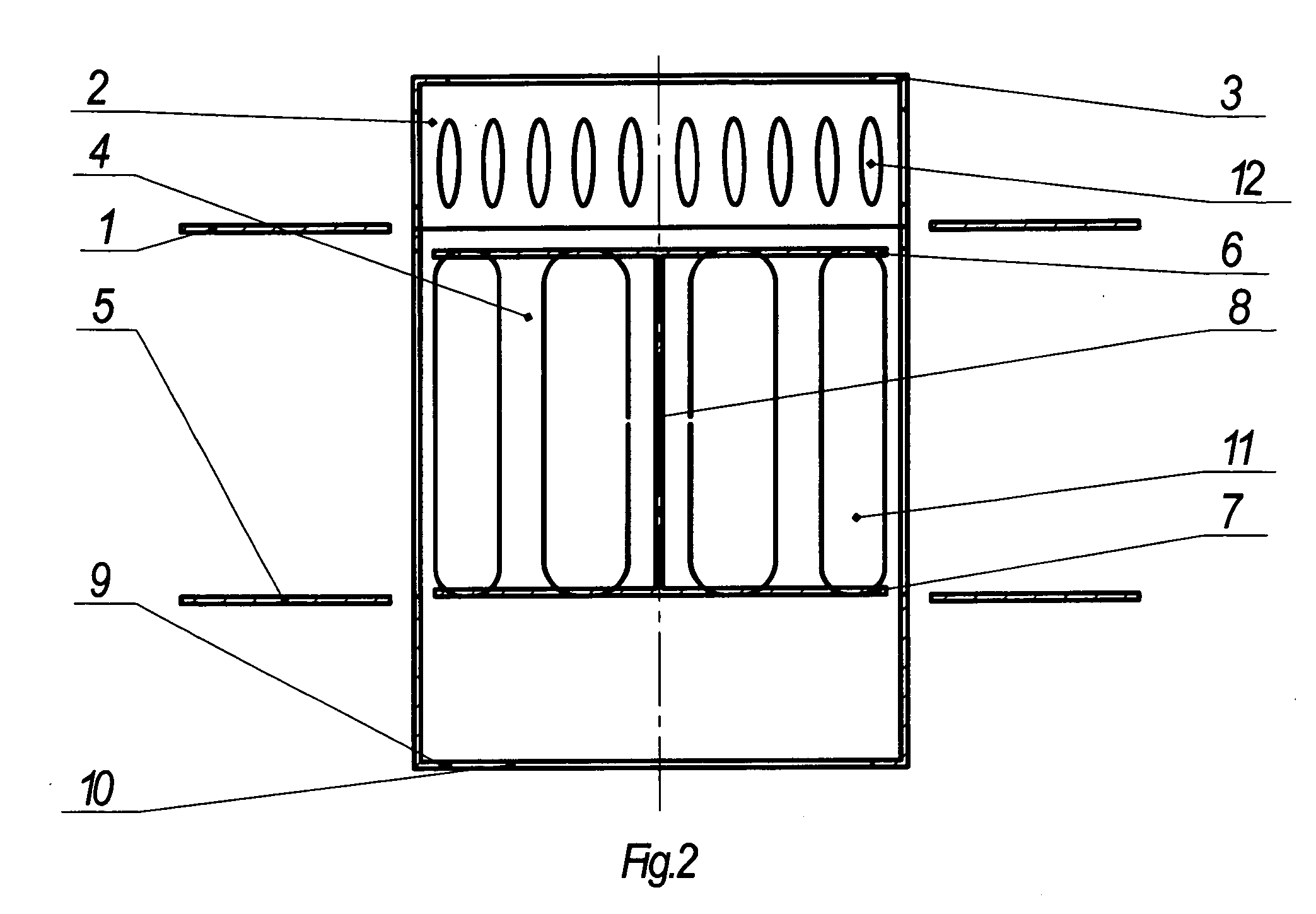
[0019]As illustrated on FIGS. 1,2,3, the inventive mass-exchange contact device comprises an essentially flat ring-shaped upper tray (1) attached with its outward edge to the walls of a conventional rectification column (not illustrated).

[0020]The inventive device comprises a cylindrical sleeve (4) attached to the inward edge of the upper tray 1, the sleeve 4 includes a top opening with a ring-shaped ascending limiter (3) surrounding the top opening, and a bottom opening (10) with a ring-shaped descending limiter (9) surrounding the bottom opening. The limiters 3 and 9 can be made as folded edges of the sle...


PUM


Abstract

A mass-exchange contact device is proposed, comprising: upper and lower flat ring-shaped trays outwardly attached to a column, a sleeve including sidewalls attached to the trays and having windows made therein with bottom edges in the plane of the lower tray, a barbotage unit connected to the top of sleeve and having orifices in its sidewalls, a movable double-acting valve including two upper and lower plates attached to a rod axially disposed therebetween. The top of barbotage unit includes an ascending limiter of valve's movement, the bottom of sleeve includes a descending limiter of the valve's movement. In some embodiments, the barbotage unit is made as a portion of the sleeve. The height of windows preferably is equal to the height of valve. The proposed design significantly improves device operation for a cyclic mode, reliability, durability, reduces its weight and cost, extends its operational range for steam and liquid loads.

Description

CROSS-REFERENCE TO RELATED APPLICATIONS[0001]This application is a U.S. national phase application of a PCT application PCT / UA2007 / 000038 filed on 7 Jun. 2007, published as WO2007 / 145604, whose disclosure is incorporated herein in its entirety by reference, which PCT application claims priority of a Ukrainian patent application UA2006 / 06612 filed on 13 Jun. 2006.FIELD OF THE INVENTION[0002]The invention is related to mass-exchange devices, namely to the devices intended for conducting mass-exchange processes in gas (steam)—liquid phase systems under conditions of a cyclical regime (where there are provided separate movements of the phases in a column). It can be used in the food, chemical, petrochemical, oil-processing, and other industries.BACKGROUND OF THE INVENTION[0003]There is known a mass-exchange contact device, comprising a tray with a contact element, a ring, a movable double-acting valve, ascending and descending limiters. The ring along its perimeter has a plurality of ve...

Claims


Application Information

Patent Timeline
IPC IPC(8): B01D3/26B01D3/20
CPCB01D3/20B01D3/163
Inventor MALETA, BOGDAN VLADIMIROVICHMALETA, OLESJA VLADIMIROVNA
Owner MALETA BOGDAN VLADIMIROVICH
Learn More