
Work device

A technology for working instruments and tools, applied in the direction of cutters, manufacturing tools, controlling mechanical energy, etc., can solve problems such as expensive

Active Publication Date: 2013-10-30
ANDREAS STIHL AG & CO KG
View PDF9 Cites 9 Cited by
  • Summary
  • Abstract
  • Description
  • Claims
  • Application Information

AI Technical Summary

Problems solved by technology

Such gears are however more expensive

Method used


Image

  • Work device
  • Work device
  • Work device

Examples


Embodiment Construction

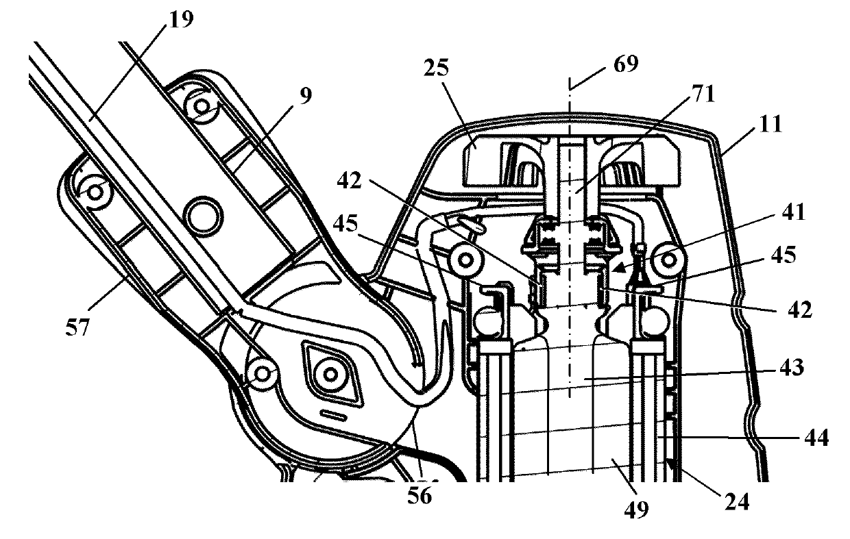
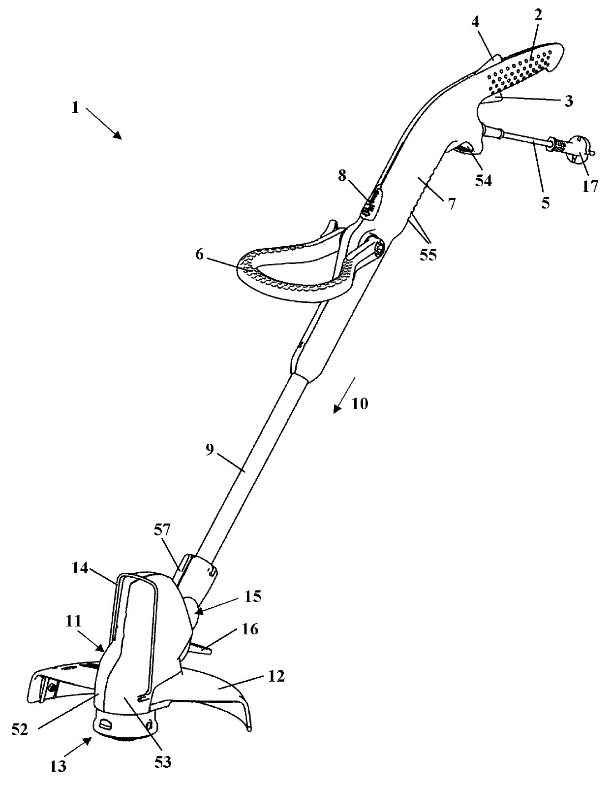
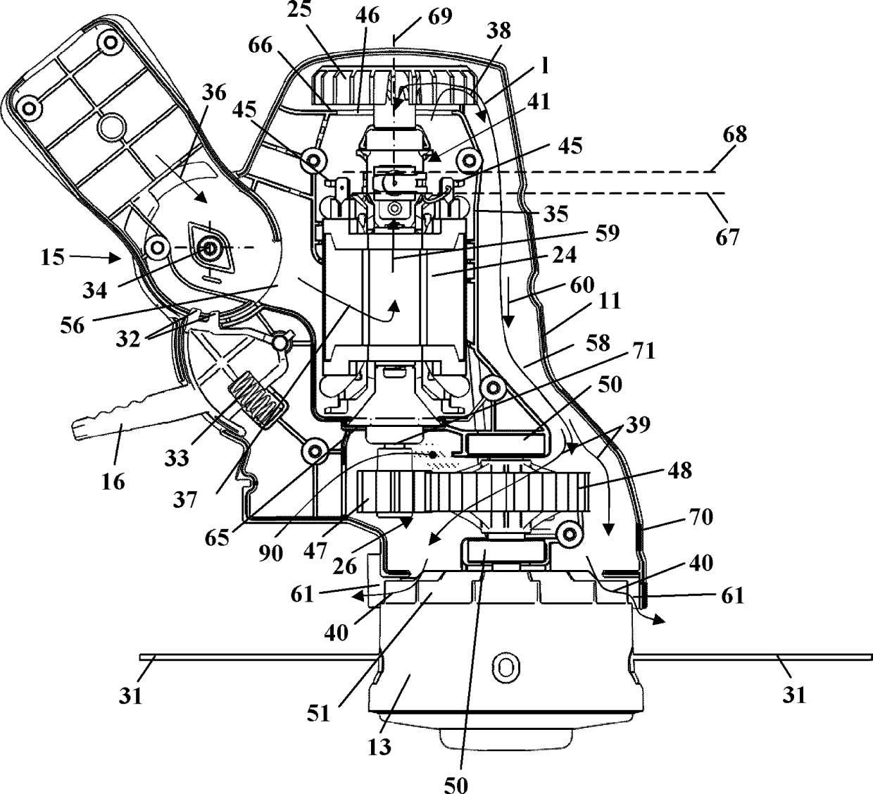
[0027] figure 1 A hand-held, hand-held power tool, ie a free-wheel cutter 1 , is shown as an example for a power tool. However, the invention can also be used in other power tools, in particular hand-held power tools such as lawn mowers. The free cutter 1 has a handle housing 7 on which the rear handle 2 is arranged. The handle housing 7 is assembled as a plastic injection-molded part from two shells which also form the rear handle 2 . A throttle lever 3 and a throttle lever lock 4 are pivotably mounted on the rear handle 2 . Protruding from the handle housing 7 is an electrical connection cable 5 , at the end of which a connection plug 17 is provided. A lead-through 54 is formed on the handle housing 7 , which is part of the strain relief described in more detail below. On its side pointing downwards during operation, the handle housing 7 has a large number of air inlet openings 55 . On the handle housing 7 , the bow handle 6 is pivotably mounted on the lower area facing...


PUM


Abstract

The working apparatus comprises a tool, which is rotatably driven by a drive motor (24) through a transmission (26). The cooling airflow moves to a coil and a commutator (41) during operation, and leaves a motor housing (35) through a passage opening (46) arranged in the flow path of the cooling airflow downstream of the commutator. The motor housing is configured to be closed at the front side (65) facing towards a transmission housing (70). The cooling airflow partially flows to the transmission housing through the flow connection.

Description

technical field [0001] The invention relates to a work implement of the type specified in the preamble of claim 1 . Background technique [0002] Electrically driven power tools are generally known, such as free cutters, lawnmowers and the like. Typically, the tool is driven by a drive motor via a transmission. For cooling the drive motor, a fan impeller is provided which guides a cooling air flow through the motor housing of the power tool. Such a power tool is known from JP 06-062637 A, namely a free-wheel cutter. [0003] It is known to encapsulate the transmission relative to the drive motor and to provide a grease filling in the transmission housing, which should ensure sufficient grease lubrication over the service life of the transmission. The packaging of the transmission should be implemented liquid-tight to prevent loss of lubricant. This results in a complex construction of the transmission. [0004] In order to be able to dispense with grease lubrication, it...

Claims


Application Information

Patent Timeline
Patent Type & Authority Applications(China)
IPC IPC(8): B25F5/00F16H57/04
CPCH02K7/145H02K9/28A01D34/78A01D34/90H02K9/06
Inventor D.克雷齐希
Owner ANDREAS STIHL AG & CO KG
Learn More