Protection Device

US20110026179A1Inactive Publication Date: 2011-02-03WEIDMULLER INTERFACE GMBH & CO KG
10 Cites 7 Cited by

Patent Information

Authority / Receiving Office
US · United States
Current Assignee / Owner
Publication Date
2011-02-03
Estimated Expiration
Not applicable · inactive patent

Smart Images

  • Figure 1
    Figure 1
  • Figure 2
    Figure 2
  • Figure 3
    Figure 3
Patent Text Reader

Abstract

An overvoltage protection circuit is provided for protecting a load against overload damage, including a coarse protection device for dissipating the major portion of the energy of the trouble event, a plurality of fine protection devices for limiting the remaining portion of the trouble energy to a safe value, a diagnostic arrangement for determining the operating condition of the destructible fine protection devices, and a disconnect arrangement for disconnecting from the protection circuit at least one of the fine protection devices that has been determined to be faulty. A trouble event identifying arrangement compares with a reference voltage standard a measured voltage existing at a measuring junction between the fine protection devices, and generates a fault signal in the event of destruction of a fine protection device. A display arrangement indicates whether or not a fine protection device has been determined to be faulty.
Need to check novelty before this filing date? Find Prior Art

Description

REFERENCE TO RELATED APPLICATIONS

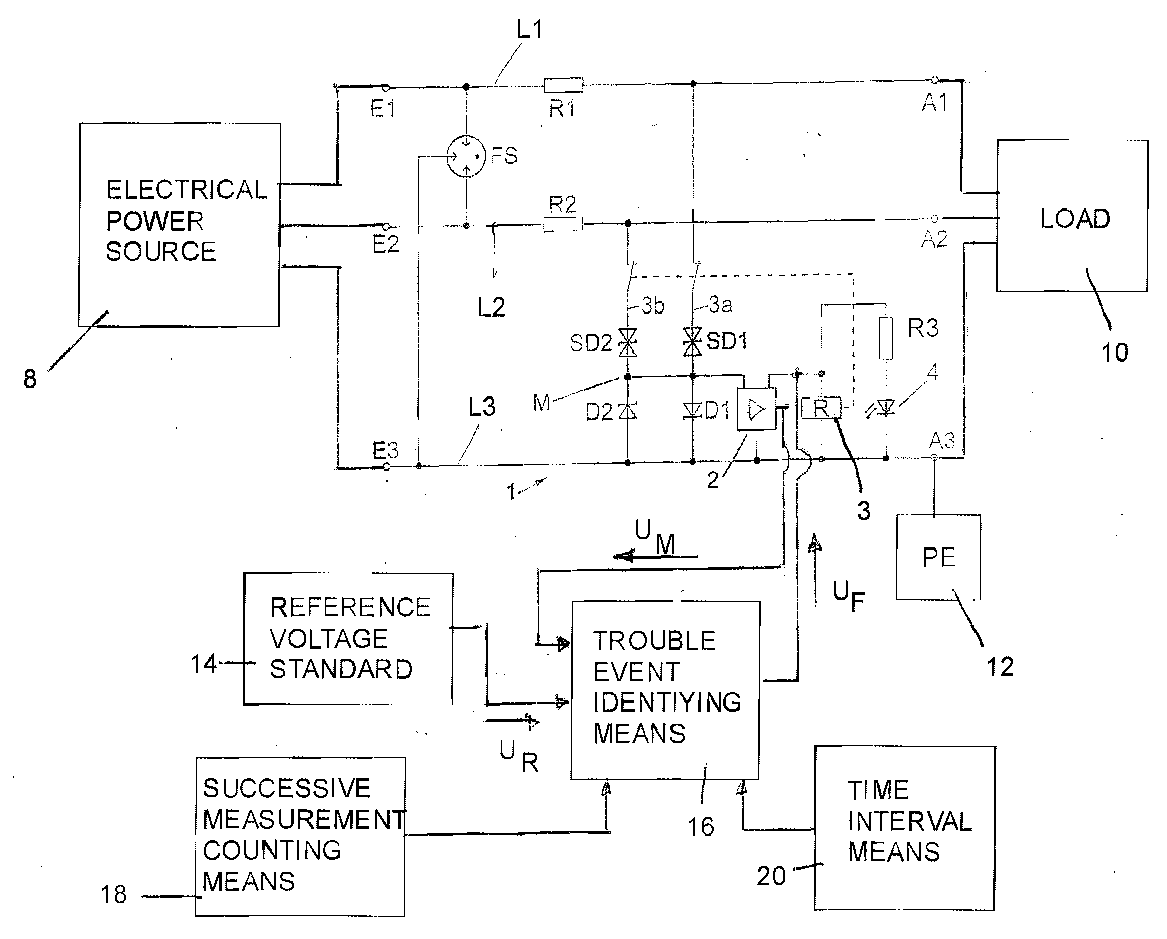
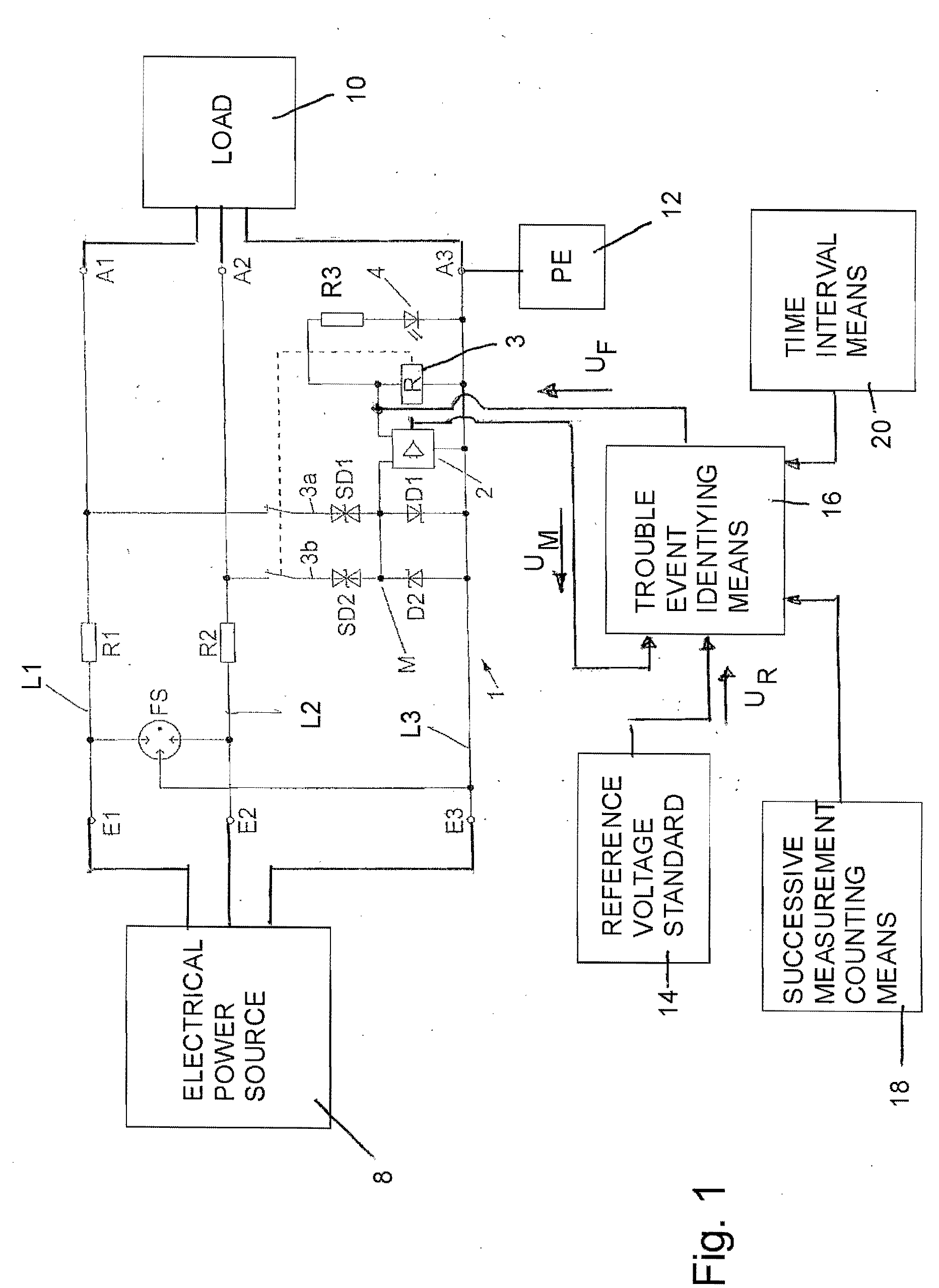
[0001] This application is a continuation of the International Application No. WO 2009 / 121799 based on PCT Application No. PCT / EP2009 / 053623 filed Mar. 26, 2009, which claims priority of the German Application No. 10 2008 016 589.1 filed Mar. 31, 2008. It is related to the inventor's companion U.S. application Ser. No. ______ filed ______ [Attorney's Docket No. 50039].BACKGROUND OF THE INVENTION

[0002] 1. Field of the Invention

[0003] An overvoltage protection circuit is provided for protecting a load against overload damage, including a coarse protection device for dissipating the major portion of the energy of the trouble event, a plurality of fine protection devices for limiting the remaining portion of the trouble energy to a safe value, a diagnostic arrangement for determining the operating condition of the destructible fine protection devices, and a disconnect arrangement for disconnecting from the protection circuit at least one of the fine protect...

Examples

Embodiment Construction

[0024]Referring first more particularly to FIG. 1, the protection circuit 1, which may be in the form of a module, includes three lines L1, L2, L3 having input terminals E1, E2, E3, respectively, connected with a voltage source 8 (for example, an electric power main, depending upon the intended use), and output terminals A1, A2, A3, respectively, connected with the load 10 (for example, an amplifier or an industrial printed circuit board). Lines L1 and L2 contain series connected resistors R1 and R2, respectively. In order to absorb the majority of the electrical energy generated by the trouble event, a gas-filled housing FS is provided having means connected to define a first spark gap between the third and first lines L3 and L1, and a second spark gap between the third and second lines L3 and L2. This part of the protective device is referred to as the coarse protection and “wipes out” the majority of the energy that is coupled into the protective device 1 as a result of a disrupt...