Installation For Candling Eggs And Optoelectronic System For Examining Under Radiation Such An Installation

a technology of optoelectronic system and installation, which is applied in the field of visiometric examination, to achieve the effect of increasing the number of illumination cycles

Active Publication Date: 2009-08-13
VISIONERF
View PDF11 Cites 25 Cited by
  • Summary
  • Abstract
  • Description
  • Claims
  • Application Information

AI Technical Summary

Benefits of technology

[0019]It therefore becomes necessary to be able to avoid risks of glare for the detection sensor, while preserving the possibility of fine discriminations between light intensities at levels relatively close to one another, that is, to avoid a strong contrast, which seems completely contradictory.
[0030]Thus, in the case where the cells present a quincunx configuration, it is advantageous to group the rows of cells two by two, providing a light source made up of a number of LED that is twice the number of cells per row. In this configuration, each diode is activated in correspondence with the passage in its field of one row of cells out of two. In other words, in this configuration, half of the diodes are associated with even-numbered lines of cells, and the other half with odd-numbered lines.
[0033]It can also be useful, however, to conduct a more thorough analysis by working in more than two stages. In particular, the invention makes it possible to draw up useful statistics by recording the results in computerized databases and submitting them to specially adapted computations to determine such data as the profitability of fertilization or the quality of a delivery received in a hatchery.

Problems solved by technology

Especially in the case of an installation in which the egg crates are treated linearly in a marking station after the visiometric examination station, the problem arises of being able to mark the eggs efficiently and rapidly by directly utilizing the signal produced by numerical processing of the images captured by the visiometric examination while taking care not to risk breaking the egg shells.

Method used


Image

  • Installation For Candling Eggs And Optoelectronic System For Examining Under Radiation Such An Installation
  • Installation For Candling Eggs And Optoelectronic System For Examining Under Radiation Such An Installation
  • Installation For Candling Eggs And Optoelectronic System For Examining Under Radiation Such An Installation

Examples


Embodiment Construction

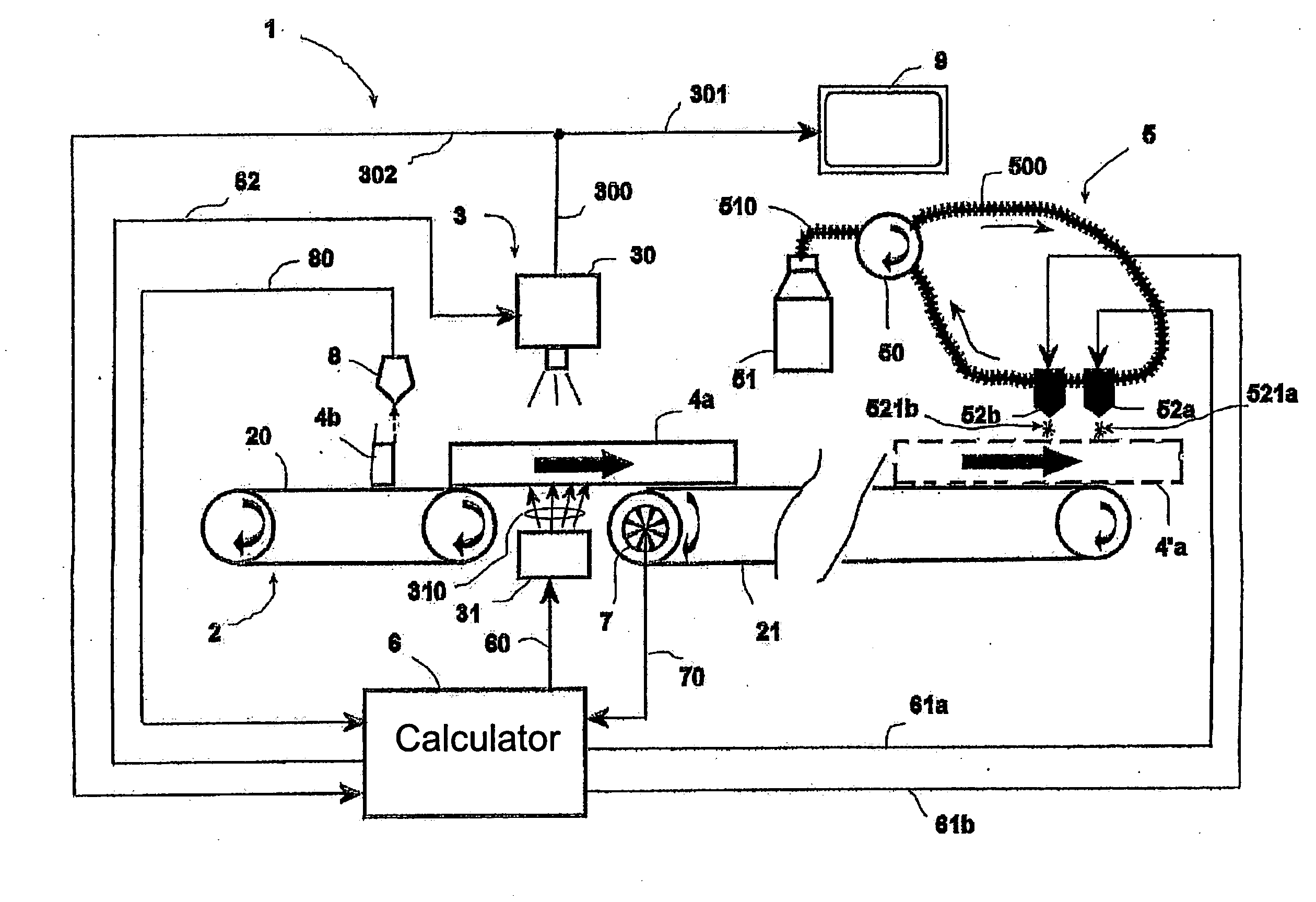
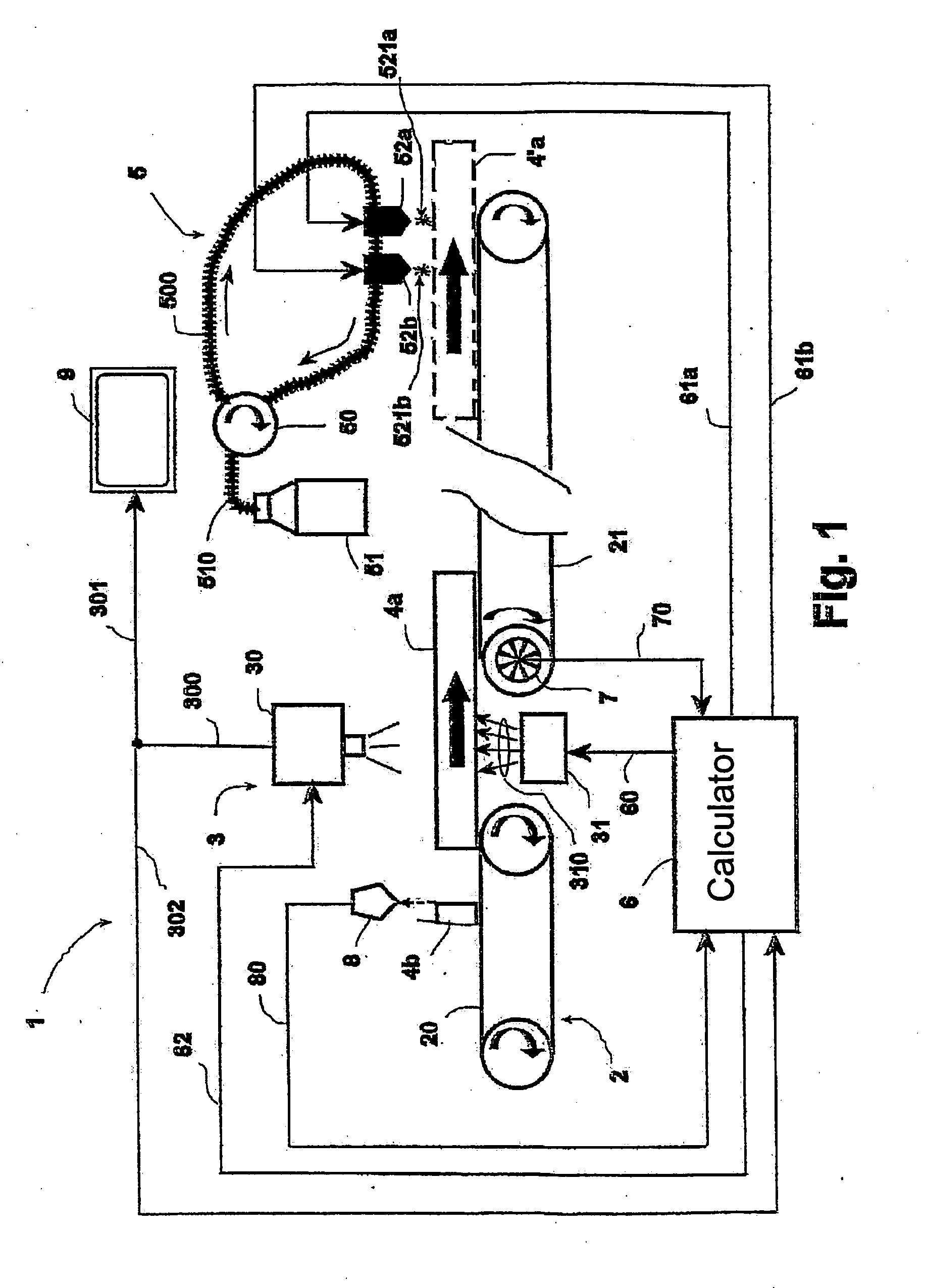
[0044]Before describing, with reference to FIG. 1, the functioning of the optoelectronic system that includes an automatic detection apparatus and an analysis apparatus for fertilized eggs in the strict sense, we describe here an example of the layout of an egg-candling installation 1 incorporating such a system, according to a preferred embodiment of the invention. In the figures that follow the common elements bear the same reference numbers and are re-described only as necessary.

[0045]With the exception of advantageous characteristics specific to the invention, which will be pointed out in detail below, the general layout of such an installation in for the most part basically common to those installations known in the art. Reference is made to the French patent 2 768 517, for instance. It is an additional advantage of the system of the invention that permits re-utilization of well-known technologies and of material that is financially amortized.

[0046]Thus the installation 1 compr...


PUM

PropertyMeasurementUnit
currentaaaaaaaaaa
currentaaaaaaaaaa
timeaaaaaaaaaa

Abstract

The invention relates to a system applicable to an installation for candling eggs, to determine the presence of fertilized eggs in the cells of the egg crate grid moving on a conveyor. Row by row, the analyzing device synchronously monitors the light emission on the eggs of the row and detection of the attenuated light of emerging beams. The monitoring includes at least two close cycles of light emission. During the first cycle, which is of short duration to avoid causing glare of the detectors of the detecting device, the coordinates of possible empty cells in a row are determined and stored. During the second cycle, which is of longer duration, the coordinates of fertilized eggs of the row are determined and stored. The egg candling installation advantageously also marks the eggs, depending in particular on whether they are fertilized or not.

Description

CROSS-REFERENCE TO RELATED APPLICATIONS[0001]The present application is a continuation of pending International patent application PCT / FR2006 / 002895 filed on Dec. 22, 2006 which designates the United States and claims priority from French patent application 0513252 filed on Dec. 23, 2005 and 0600018 filed on Jan. 3, 2006, the content of which is incorporated herein by reference.FIELD OF THE INVENTION[0002]The invention relates to techniques for visiometric examination applied to objects arranged for examination in defined discrete locations and in successive rows, in a continuous series following a regular spatial distribution that is repeated periodically. The concept of visiometric examination is taken here as including all techniques of the optoelectronic type that involve the capture of an image that detects a light beam coming from each object submitted to examination under incident rays, as well as an analysis by image processing on the received signals, controlled by adapted ...

Claims


Application Information

Patent Timeline
Patent Type & Authority Applications(United States)
IPC IPC(8): B41J3/00G01N33/08
CPCA01K43/10B07C5/342G01N33/085B41J3/407B41J3/4073B07C5/38A01K43/00
Inventor ROBERT, PIERRESOMVILLE, OLIVIER
Owner VISIONERF
Why Eureka
Try Eureka