
Airflow conducting structure

Inactive Publication Date: 2009-08-13
INVENTEC CORP
View PDF8 Cites 5 Cited by
  • Summary
  • Abstract
  • Description
  • Claims
  • Application Information

AI Technical Summary

Benefits of technology

[0008]In view of the disadvantages of the prior art mentioned above, it is an objective of the present invention to provide an airflow conducting structure, which provides a better heat dissipating efficiency without increasing the volume of a device.
[0009]It is another objective of the present invention to provide an airflow conducting structure for lowering the cost of heat dissipation.
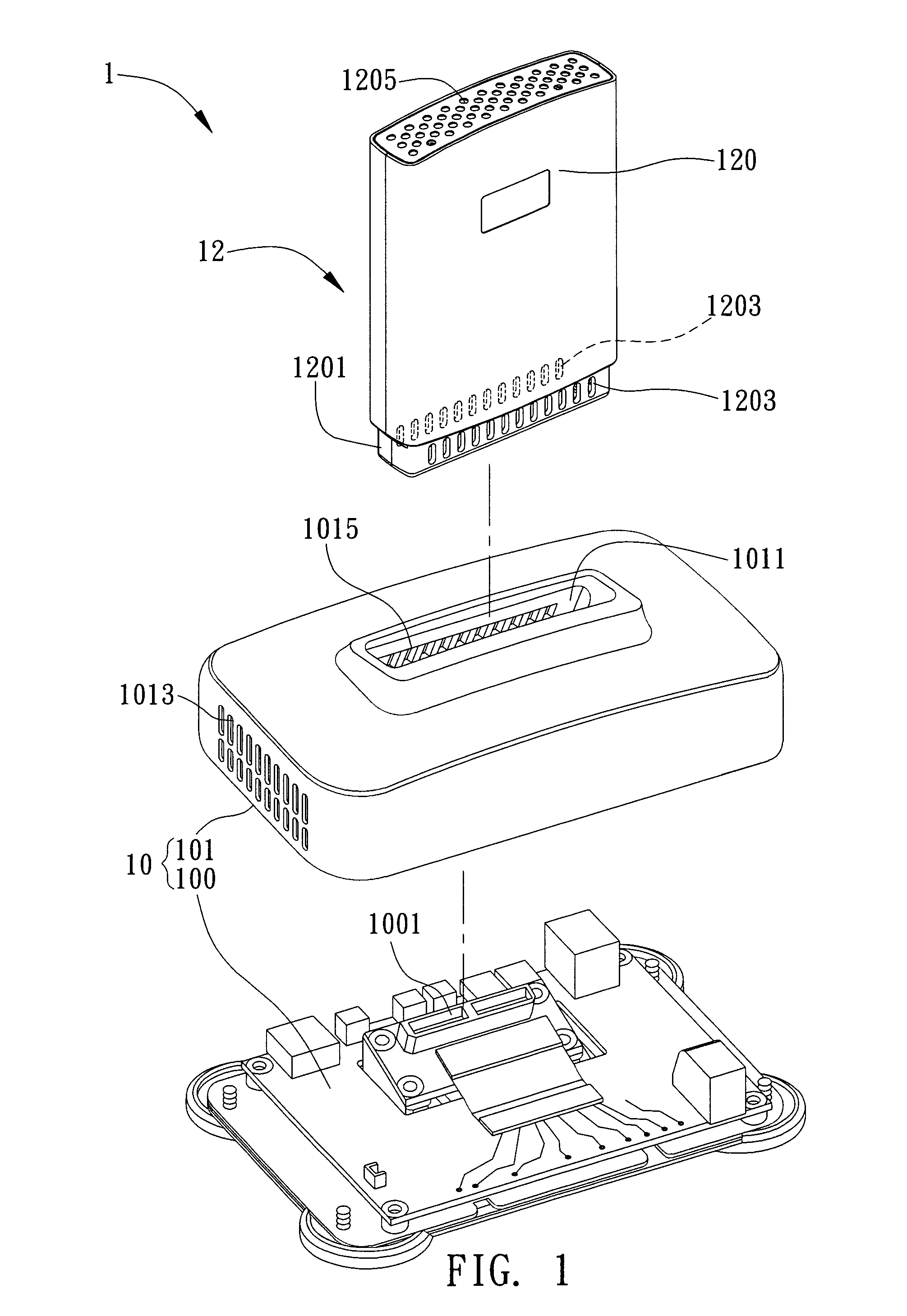
[0013]Compared with the prior art, the airflow conducting structure of the present invention provides a chimney-like airway by disposing airflow inlets and airflow outlets on the base and the control box of the electronic device, so that the objective of heat dissipation is achieved based on the principle that hot air is lighter than cold air to conduct the airflow through the base and the control box of the electronic device. Accordingly, a better heat dissipating efficiency is achieved without increasing the overall volume of the electronic device. In addition, since the present invention omits some heat dissipating units and provide a better heat dissipating efficiency, the components and the cost required for heat dissipation can be relatively decreased.

Problems solved by technology

However, if the above conventional heat dissipating method is used, the volume of the electronic device must be increased.
On the contrary, if a smaller heat dissipating unit is used, space-saving can be achieved, but the cost will be increased, more interior components in the electronic device are needed, and the structure is relatively getting complicated.

Method used


Image

  • Airflow conducting structure
  • Airflow conducting structure
  • Airflow conducting structure

Examples


Embodiment Construction

[0019]The following illustrative embodiments are provided to illustrate the disclosure of the present invention. These and other advantages and effects can be apparently understood by those in the art after reading the disclosure of this specification. The present invention can also be performed or applied by other different embodiments. The details of the specification may be on the basis of different points and applications, and numerous modifications and variations can be devised without departing from the spirit of the present invention.

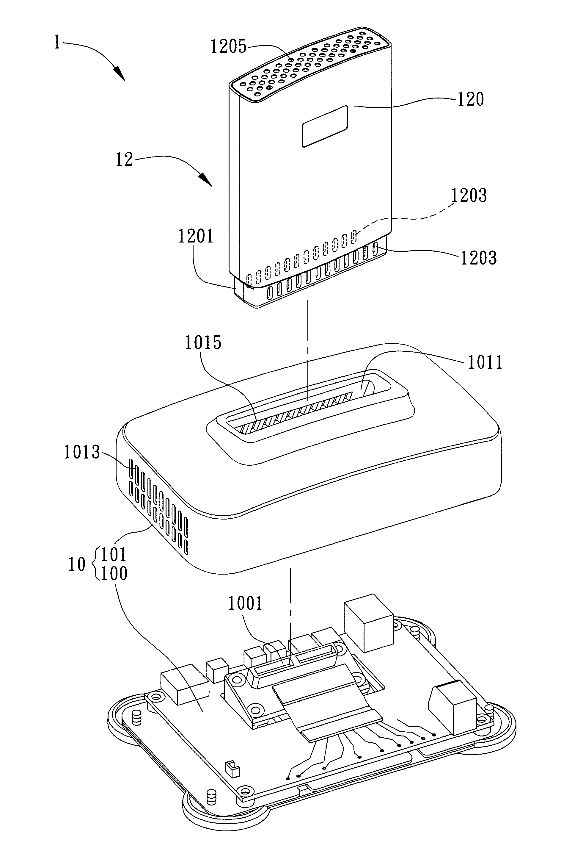
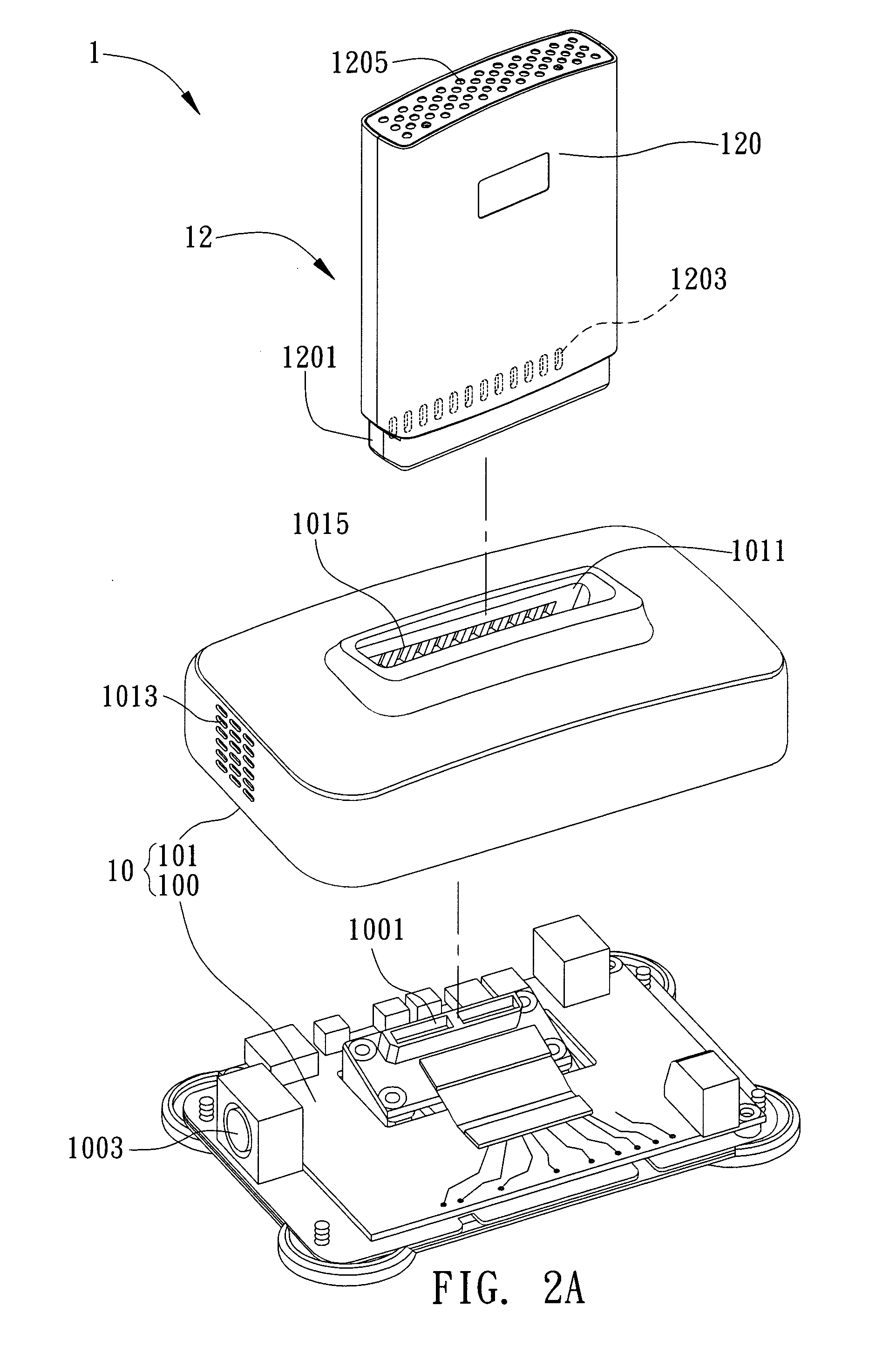
[0020]Referring to FIG. 1, it is an exploded view showing the airflow conducting structure of the present invention. It should also be noted that all illustrated drawings are simplified and are for illustrating elements related to the present invention only. These elements are not shown based on the practical ratio, number, shape, and size. In practice, the number, shape, and size can be varied, and the layout of these elements can be more compli...


PUM


Abstract

The present invention provides an airflow conducting structure for an electronic device having a base and a control box. The control box is inserted in and mounted on the base, and a first connection section is disposed in a grooved top of the base. The control box has a box body, a heat generating source disposed in the box body, and a second connection section disposed on the bottom of the box body for being connected to the first connection section. The airflow conducting structure includes airflow inlets and airflow outlets that are respectively disposed on the base and the control box, so as to form a chimney-like airway. Therefore, a better heat dissipating efficiency is achieved without increasing the volume of the electronic device.

Description

BACKGROUND OF THE INVENTION[0001]1. Field of the Invention[0002]The present invention relates to an airflow conducting technique, and more particularly to an airflow conducting structure for electronic devices.[0003]2. Description of Related Art[0004]The heat dissipating problem of an electronic device has become a major factor for deciding the performance and quality of an electronic device. In a sort of electronic devices, a heat dissipating system that has a better heat dissipating capability is undoubtedly more popular. While designing an electronic device, designs for the interior and the exterior of the electronic device are correspondingly taken into consideration for enhancing heat dissipating efficiency.[0005]In a conventional method for heat dissipation, a heat dissipating unit such as heat sink, heat pipe, fan, and the like is installed at a position where corresponds to the heat generating source in an electronic device, and a heat dissipating hole corresponding to the a...

Claims


Application Information

Patent Timeline
IPC IPC(8): H05K7/20
CPCH05K7/20127G06F1/20
Inventor GUO, GUANG-LIANGLIU, WEN-JIECHENG, TSAI-KUEI
Owner INVENTEC CORP
Learn More