Three-dimensional shape data position matching method and device

a three-dimensional shape and position matching technology, applied in image data processing, instruments, reradiation, etc., can solve the problems of inability to measure the back surface of the object, limited precision of positional relationships, and limit the size of the object to be measured, etc., to achieve accurate position matching without cumulative errors, low calculation amount, and large error

Inactive Publication Date: 2009-08-13
IHI CORP
View PDF4 Cites 16 Cited by
  • Summary
  • Abstract
  • Description
  • Claims
  • Application Information

AI Technical Summary

Benefits of technology

[0031]The present invention was invented to resolve the problems described above. That is, the object of the present invention is to provide a three-dimensional shape data position matching method and device capable of accurate position matching without cumulative error and with low calculation amount, even

Problems solved by technology

When measuring the three-dimensional shape of an object and restoring that three-dimensional shape, it is possible to acquire surface data of the surface facing the observation point (measurement position) when measuring from a single observation point, but not possible to measure the back surface of the object.
Methods for obtaining the positional relationships between the observation point and the object to be measured include methods wherein the object is placed on a stage and rotated, and methods wherein the observation point is held on an arm, or the like, that has a mechanical linkage, but in both cases the precision of the positional relationships is limited.
Additionally, even assuming precision were adequate, there is still a limit to the size of the object to be measured.
Moreover, with this type of range sensor, typically there is error of about ±20 cm in the measured distances.
Since the measured position is different for each measurement, there are

Method used


Image

  • Three-dimensional shape data position matching method and device
  • Three-dimensional shape data position matching method and device
  • Three-dimensional shape data position matching method and device

Examples


Embodiment Construction

[0099]A preferred embodiment of the present invention will be explained below with reference to the drawings. Note that in each drawing, common portions are assigned same reference numeral, and redundant explanations are omitted.

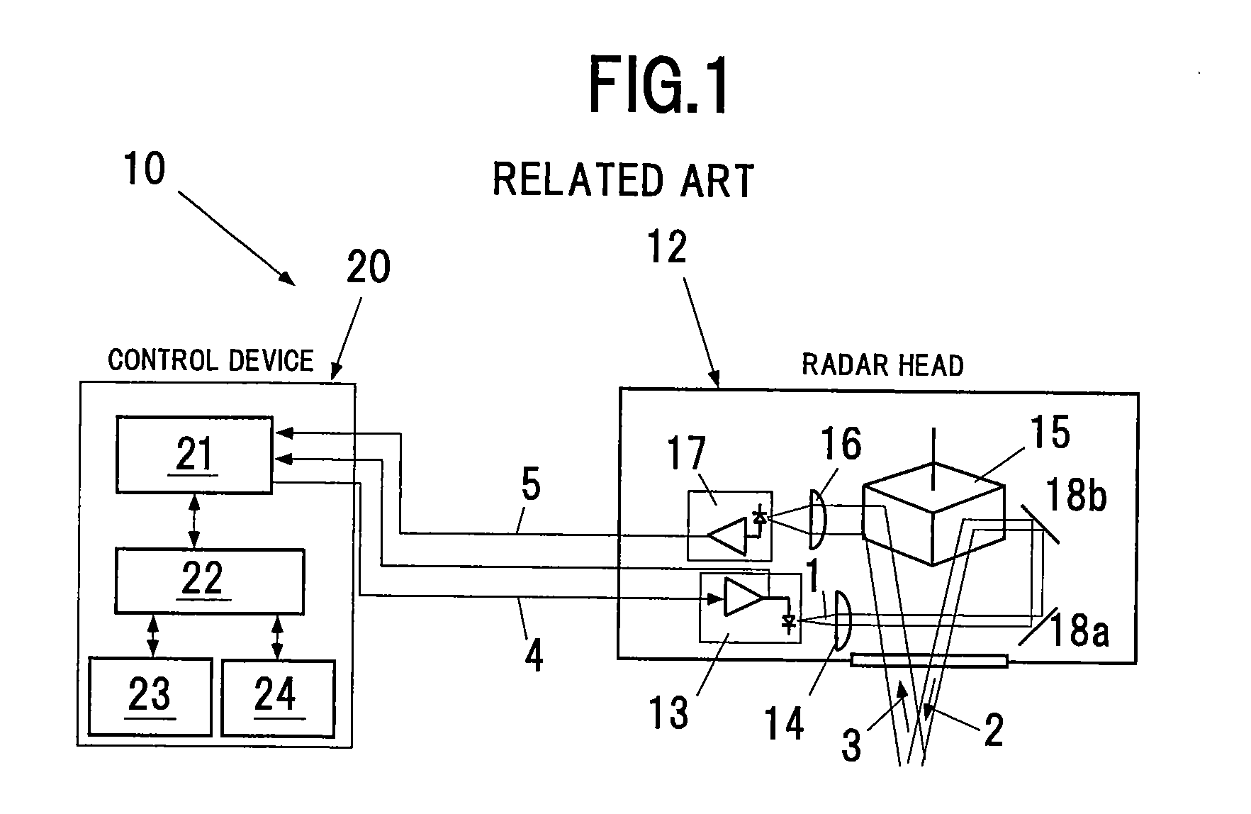
[0100]FIG. 1 is a structural diagram of a three-dimensional laser radar as one example of a range sensor. A three-dimensional laser radar is disclosed in, for example, non-patent document 3.

[0101]As is illustrated in the drawing, the three-dimensional laser radar 10 is structured from a radar head 12 and a control device 20. A pulse laser beam 1 generated from a laser diode 13 is shaped into a collimated beam 2 by a projection lens 14, is scanned in two-dimensional directions by mirrors 18a and 18b and polygon mirror 15, which rotates and swings, to illuminate the object to be measured. The pulse laser beam 3 that is reflected from the object to be measured is focused by photo receiver lens 16 via the polygon mirror 15, to be converted into an electrical sig...


PUM


Abstract

A three-dimensional shape data position matching method for measuring a static three-dimensional shape from a plurality of measuring positions, and for combining and position matching the distance data thereof, including: a data inputting step S1 for inputting, into a computer, coordinate values on a three-dimensional shape at a new measuring position; a model structuring step S4 for structuring an environment model that partitions a spatial region in which the three-dimensional shape exists, into a plurality of voxels formed from rectangular solids, of which the boundary surfaces are mutually perpendicular, and stores the positions of the individual voxels; a matching step S5 for setting and recording a representative point and an error distribution thereof, within the voxel corresponding to the coordinate value; a fine matching step S7 for position matching so as to minimize the summation of the distances between adjacent error distributions by rotating and translating a new measured data and error distribution, or rotating and translating an environment model for a new measuring position, relative to an environment model for a previous measuring position; and an outputting step for outputting, to an outputting device, the voxel position, the representative point, and the error distribution.

Description

BACKGROUND OF THE INVENTION[0001]1. Technical Field of the Invention[0002]The present invention relates to a three-dimensional shape data position matching method and device for measuring a non-moving three-dimensional shape from a plurality of measuring positions, and for combining and position matching the distance data thereof.[0003]2. Description of the Related Art[0004]In the present invention, the estimation of geometric positional relationships of a plurality of range images that are obtained by measuring a non-moving three-dimensional shape from multiple observation points is termed “position matching.”[0005]Three-dimensional shape measuring technologies are becoming more prevalent, and three-dimensional shape data is used in a variety of application fields, such as measuring shapes inmachine components / workpieces, self-position identification in mobile robots, and topographical and structural measurements, and the like.[0006]When measuring the three-dimensional shape of an ...

Claims


Application Information

Patent Timeline
IPC IPC(8): G06K9/46G06T19/00
CPCG01B11/24G06T17/005G01S17/89
Inventor HAYASHI, TOSHIHIROKAWANO, YUKIHIROTERADA, HIDEO
Owner IHI CORP
Why Eureka
Try Eureka