
Mechanical method for improving bond joint strength

Active Publication Date: 2009-08-13
ZEPHYROS INC
View PDF61 Cites 64 Cited by
  • Summary
  • Abstract
  • Description
  • Claims
  • Application Information

AI Technical Summary

Benefits of technology

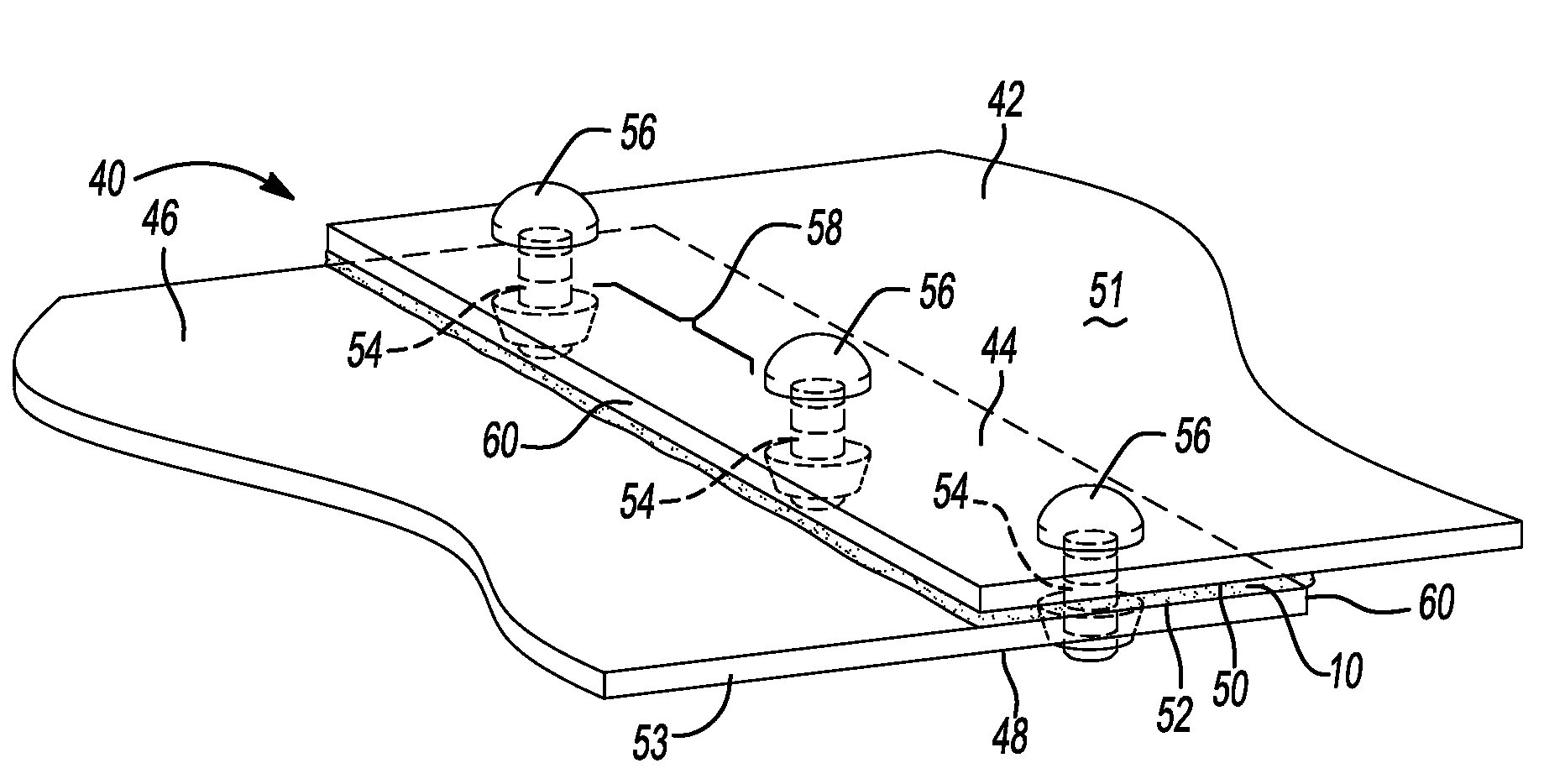
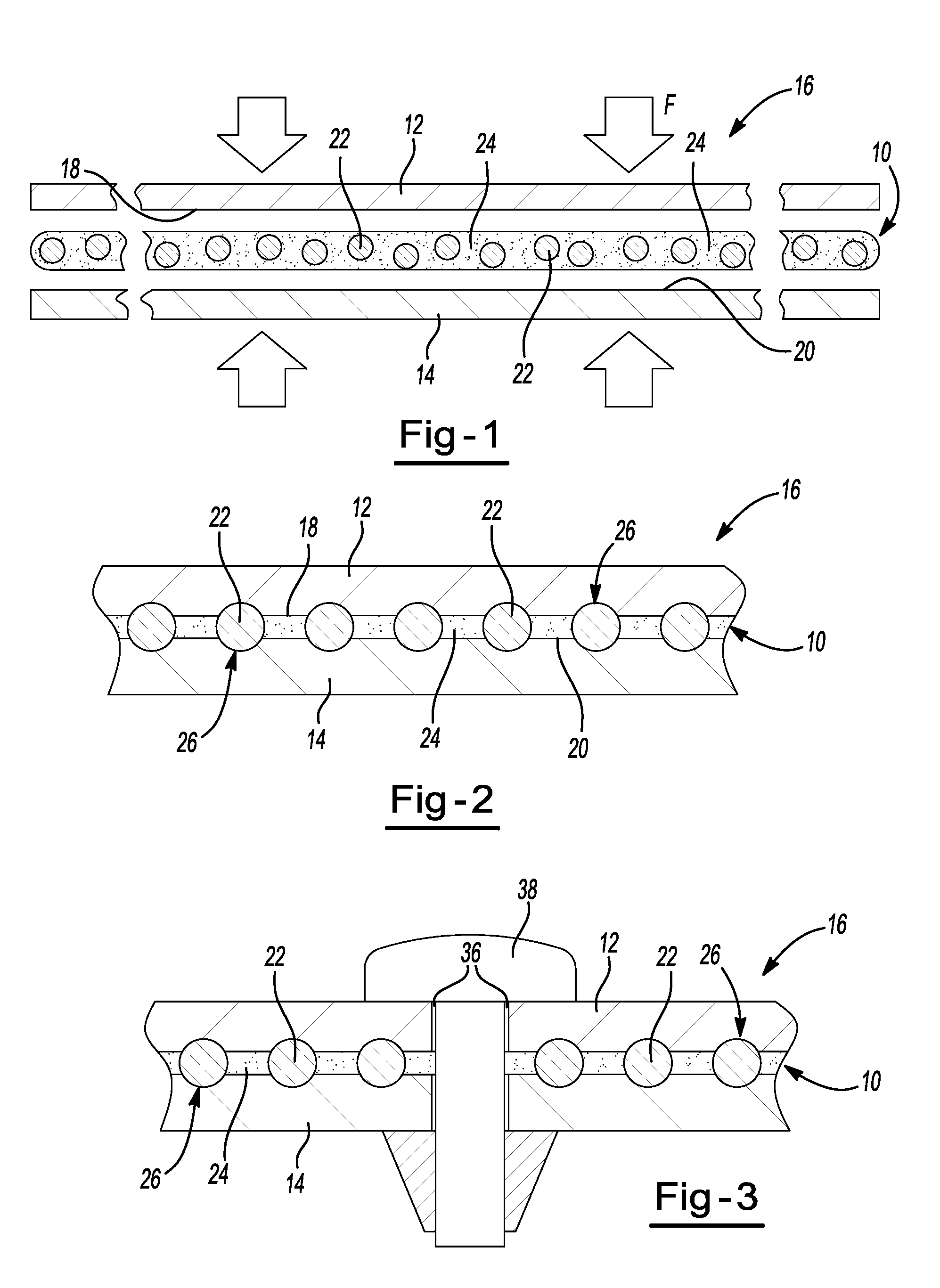
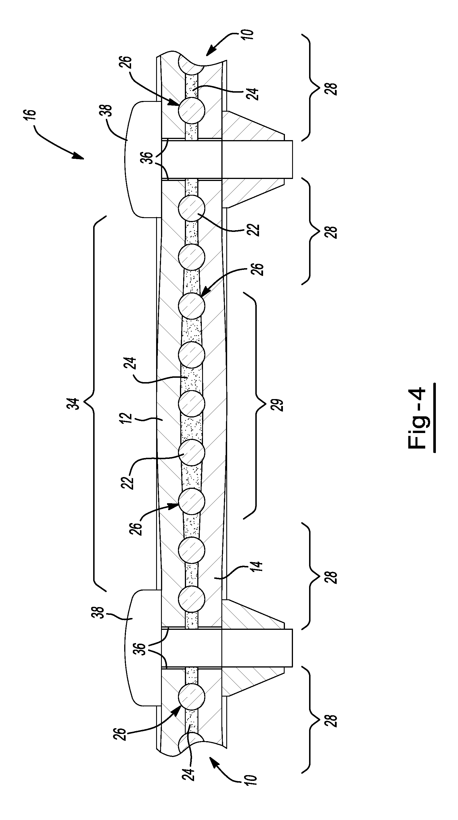
[0004]The present invention seeks to improve upon prior joint assemblies and particularly reducing the amount of slippage therebetween by providing a method for improving joint strength between a first and second member that includes the steps of providing a first member having a first connection region with an internal and external surface. The sealant material includes a matrix material at least partially encasing rigid components that is applied to the internal surface of the first connection region. A second member having a second connection region with an internal and external surface is positioned such that the first and second connection regions overlap with the sealant material being located therebetween. The first and second members are joined upon an application of force that is applied through the use of one or more fasteners thereby displacing the sealant material to allow direct contact between the rigid components and both internal surfaces of the first and second connection regions so that a depression is formed by plastic deformation in both the first and second connection regions by the rigid components, and a portion of the rigid components remains within the plastically deformed depression. Wherein a compressive force is applied to the exterior surface of both the first and second connection regions by the one or more fasteners while the rigid components apply an internal tension force acting opposite of the compression force to the interior surface of both the first and second connection regions proximate to the fastener to form a mechanical lock thereby reducing slippage and generally maintaining the joint in position.

Problems solved by technology

Such materials, however, suffer from drawbacks such as slippage during handing or otherwise which may weaken the joint.
For example, during the forming of the joint or installation of the structural member, the substrates of typical joints may shift so as to weaken the joint due to slippage therebetween.
Also, it is common that prior sealing devices also undergo deformation causing the sealing material to expel from the joint causing weakened portions of the joint, which may be increased at elevated temperatures.
As another example, expansion / contraction characteristics of the materials during exposure to temperature variances can limit the ability of the materials to seal and / or can degrade materials.
As another example, such materials can limit that ability of members to be attached to each other or have a limited ability to enhance the attachment of members to each other.

Method used


Image

  • Mechanical method for improving bond joint strength
  • Mechanical method for improving bond joint strength
  • Mechanical method for improving bond joint strength

Examples


examples

[0066]The sealant material including the first component (e.g., beads) may be applied to a joint (with at least one substrate near or around one or more fasteners such as a rivet) to assist in maintaining the substrate(s) in position and optionally sealing the joint from the surroundings such as water, air, or otherwise leakage.

[0067]It is believed that the sealant material of the present invention (e.g., with the first component) resulted in increased slip-load forces relative to previous sealant materials (e.g., with or without spacer materials) used in similar joint configurations as determined from lap shear testing. Slip load forces being defined as the amount of force at which a load drops off (e.g., point at which movement occurs by one substrate relative to another while in shear). Typically the substrates may be joined by mechanical means such as fasteners, chemical means such as adhesives, or both. Accordingly, it is appreciated that joints resulting in lower slip loads, p...


PUM

PropertyMeasurementUnit
Lengthaaaaaaaaaa
Lengthaaaaaaaaaa
Lengthaaaaaaaaaa

Abstract

A method for improving joint strength between a first and second member comprising the steps of: applying a sealant material including a matrix material at least partially encasing rigid components to the first and second members; joining the first and second members upon an application of force that is applied through the use of one or more fasteners; wherein a compressive force is applied to the exterior surface of both the first and second members by the one or more fasteners while the rigid components apply an internal tension force acting opposite of the compression force to the interior surface of both the first and second members proximate to the fastener to form a mechanical lock thereby reducing slippage and generally maintaining the joint in position.

Description

CLAIM OF PRIORITY[0001]The present application claims the benefit of the filing dates of U.S. Provisional Application Ser. No. 61 / 027,294, filed Feb. 8, 2008 and U.S. Provisional Application Ser. No. 61 / 027,688, filed Feb. 11, 2008, all of which are hereby incorporated by reference for all purposes.FIELD OF THE INVENTION[0002]The present invention relates to a methods and devices for improving bond joint strength, preventing joint slippage, the protection of two or more joined components from corrosion, or any combination thereof.BACKGROUND OF THE INVENTION[0003]For many years, industry has developed sealing materials and structural materials that can be located between surfaces of members for limiting exposure of those surfaces to ambient environments and / or for assisting in connecting the surfaces together. Such materials, however, suffer from drawbacks such as slippage during handing or otherwise which may weaken the joint. For example, during the forming of the joint or installa...

Claims


Application Information

Patent Timeline
IPC IPC(8): F16B11/00B32B7/08
CPCF16B5/02F16B5/04F16B19/008Y10T29/49885F16B5/00Y10T403/472Y10T29/49826F16B33/004
Inventor APFEL, JEFFREY R.
Owner ZEPHYROS INC
Learn More