Quick change tool for die casting metal

a technology of die casting metal and tool, which is applied in the direction of manufacturing tools, metal-working apparatus, shaping tools, etc., can solve the problems of time-consuming process of precisely positioning the heavy die on the platen, significant per piece cost of die casting products, and the time-consuming die casting process

Inactive Publication Date: 2009-08-20
YATES DAVID N
View PDF2 Cites 6 Cited by
  • Summary
  • Abstract
  • Description
  • Claims
  • Application Information

AI Technical Summary

Benefits of technology

[0008]According to the present invention, a novel method and tool is p

Problems solved by technology

A disadvantage to die casting is the time it takes to set up a die for use.
A significant per piece cost of die casting products comes from the cost to build the die and then the set up required each time the die is used.
Ty

Method used


Image

  • Quick change tool for die casting metal
  • Quick change tool for die casting metal
  • Quick change tool for die casting metal

Examples


Embodiment Construction

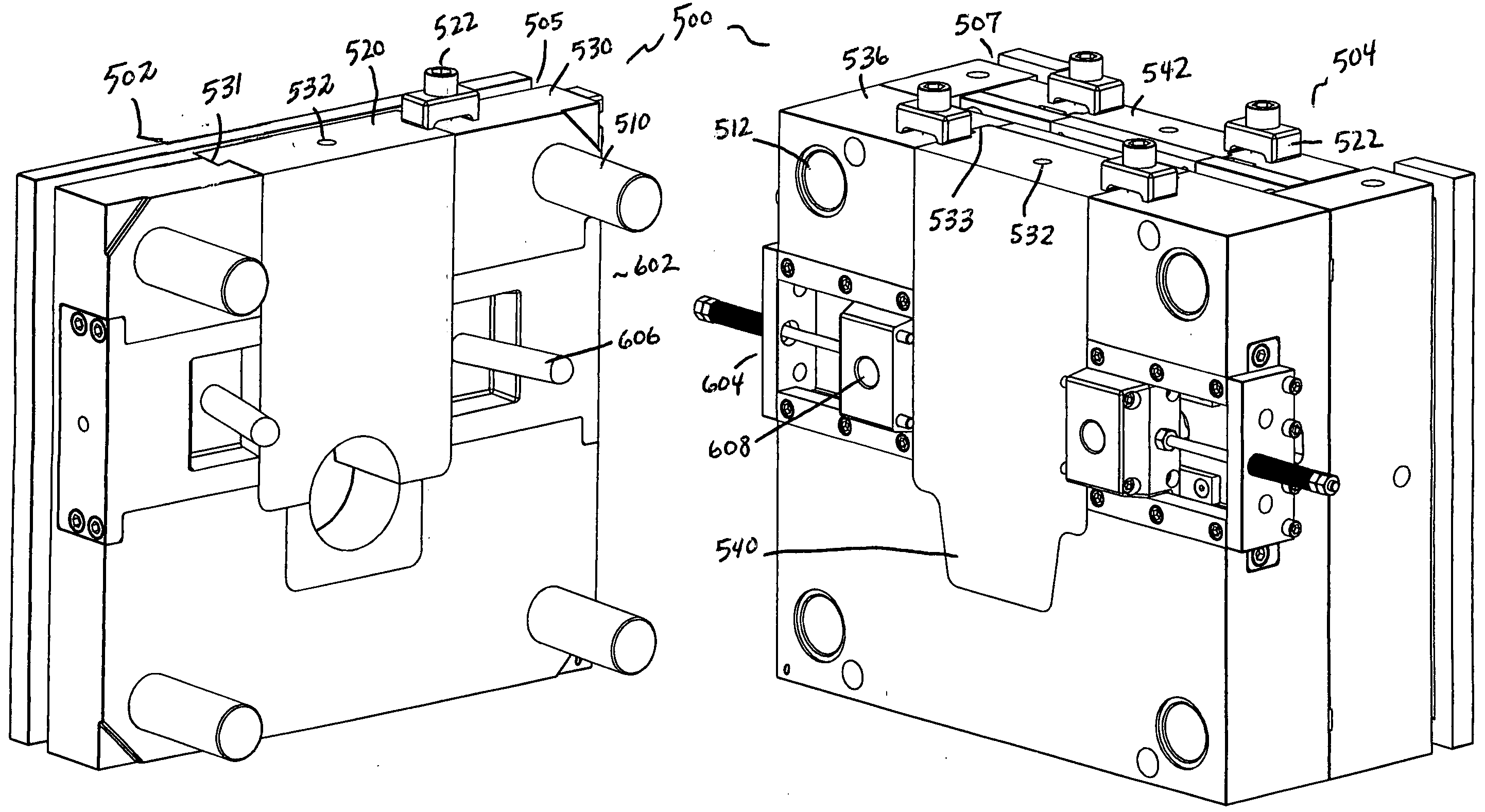
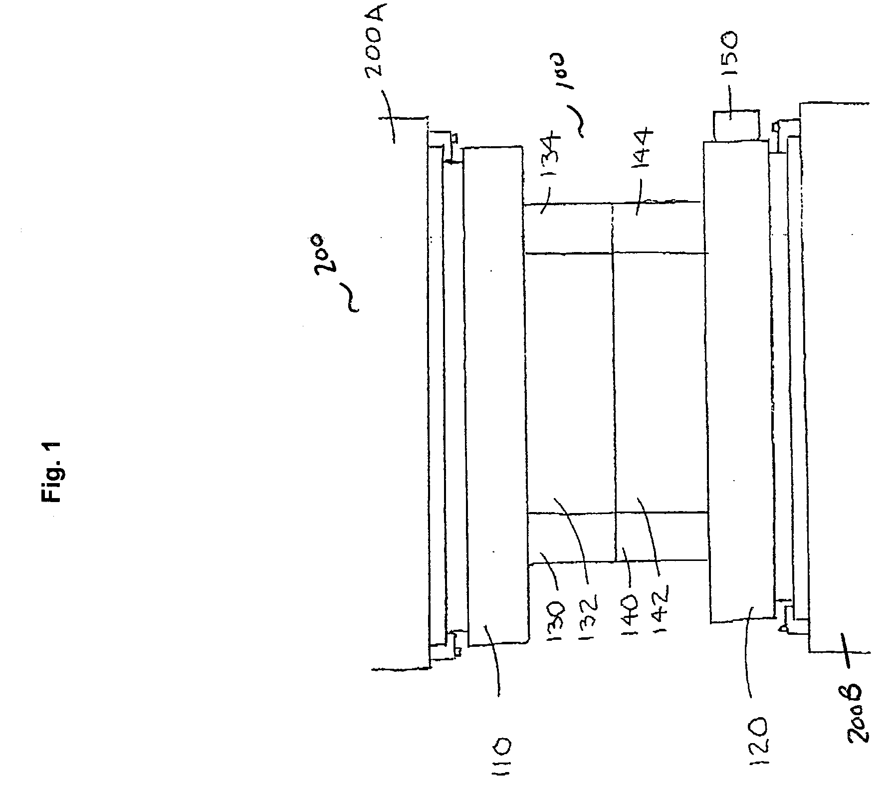
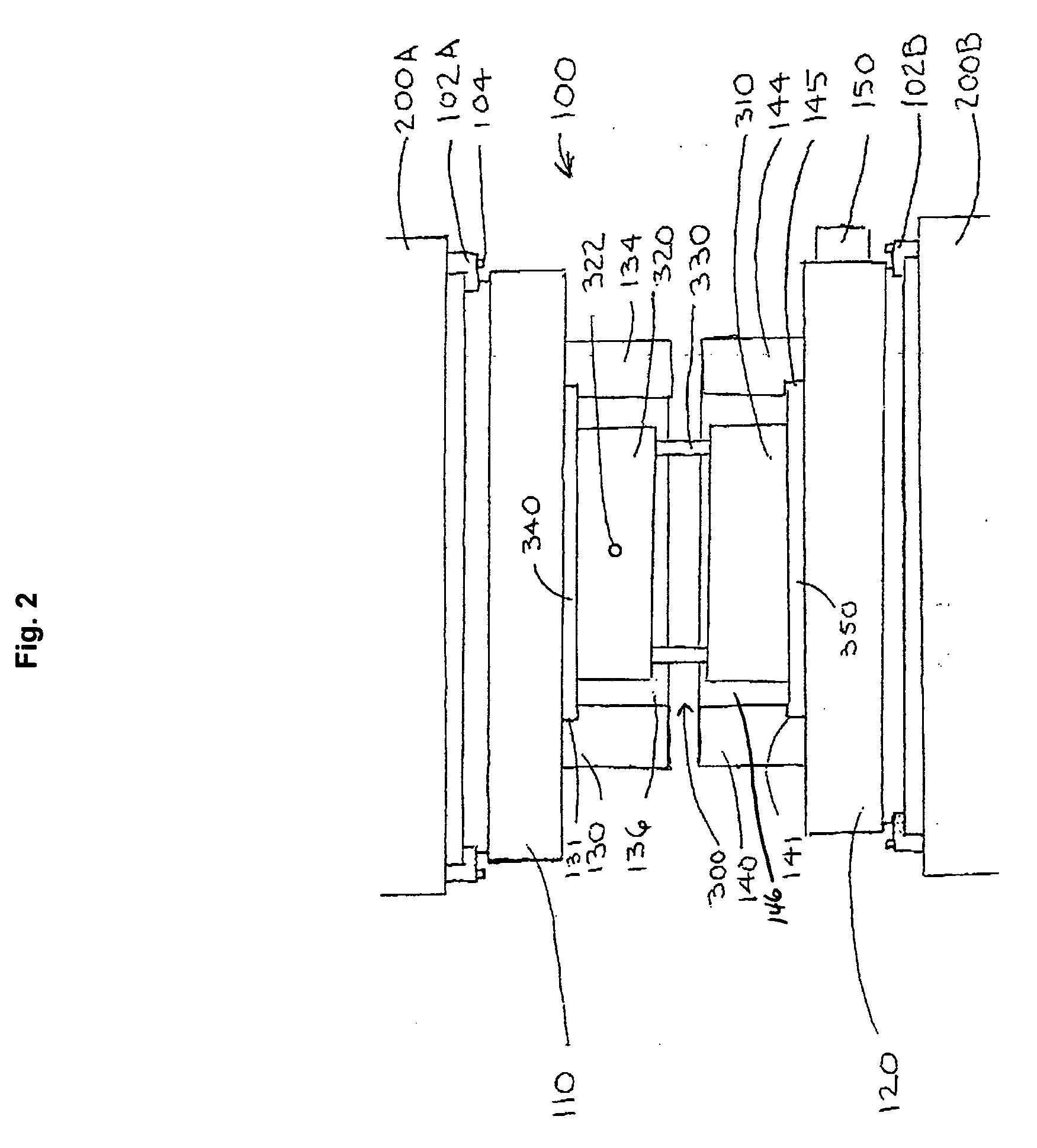
[0018]In accordance with the present invention, a quick change tool for casting metal is disclosed. The tool and method consists of components configured and correlated with respect to each other so as to attain the desired objective. FIG. 1 shows a quick change die assembly 100 mounted in a mold machine 200. The die assembly 100 mounts to the upper platen 200A and the lower platen 200B of a conventional die casting mold machine 200. Clamps 102 hold bolts 104 used to mount the die assembly 100 to the upper 200A and lower 200B platens. The clamps 102A hold an upper die shoe 110 to the upper platen 200A. The upper die shoe 110 includes a slot 112 to accommodate each clamp 102A. The lower die shoe 120 also includes a slot 122 around its perimeter to accommodate clamps 102B. The upper die shoe110 has upper die rails 130, 132, 134 and 136 bolted to it to form a plate like frame. The lower die shoe 120 has lower die rails 140, 142, 144 and 146 bolted to it to form a lower plate like frame...


PUM


Abstract

A quick change tool for use in die casting. The tool includes a pair of frame plates permanently bolted into a die casting machine. A first frame plate bolted to an upper platen of the machine and a second frame plate bolted to the lower platen. Each frame or plate can include a plurality of slotted rails that form a slotted rectangular periphery groove adapted to accept a standard size periphery ear attached to an existing die. This allows a die casting operation to retrofit old dies to fit the system while also making new dies to fit. The system allows for dies to be quickly slid out of a casting machine substantially reducing set up time in a die casting operation while still allowing for a precise relocation of the dies at each change over.

Description

CROSS REFERENCES TO RELATED APPLICATIONS[0001]U.S. Provisional Application for Patent No. 61 / 066,049, filed Feb. 15, 2008, with title “Quick Change Tool and Method for Die Casting Metal” which is hereby incorporated by reference. Applicant claim priority pursuant to 35 U.S.C. Par. 119(e)(i).[0002]Statement as to Rights to inventions made under Federally sponsored research and development: Not applicable.BACKGROUND OF THE INVENTION[0003]1. Field of the Invention[0004]This present invention relates to a method and system for casting metals. Aluminum, zinc and alloys for example are commonly die cast. Molten metal under high pressure is poured into a tool steel mold and when an aluminum part has cooled it is ejected from the tool steel mold.[0005]2. Background Information[0006]Parts can be cast from molten metal by sand casting or by die casting. Die casting has the advantage that many parts can be formed using a single tool. A disadvantage to die casting is the time it takes to set up...

Claims


Application Information

Patent Timeline
IPC IPC(8): B21D37/14
CPCB21D37/04
Inventor YATES, DAVID N.
Owner YATES DAVID N
Why Eureka
Try Eureka