

Reducing carbon dioxide (CO2) emissions from the burning of a fossil fuel
- Summary
- Abstract
- Description
- Claims
- Application Information
AI Technical Summary
Benefits of technology
Problems solved by technology
Method used
Image

Examples
Example
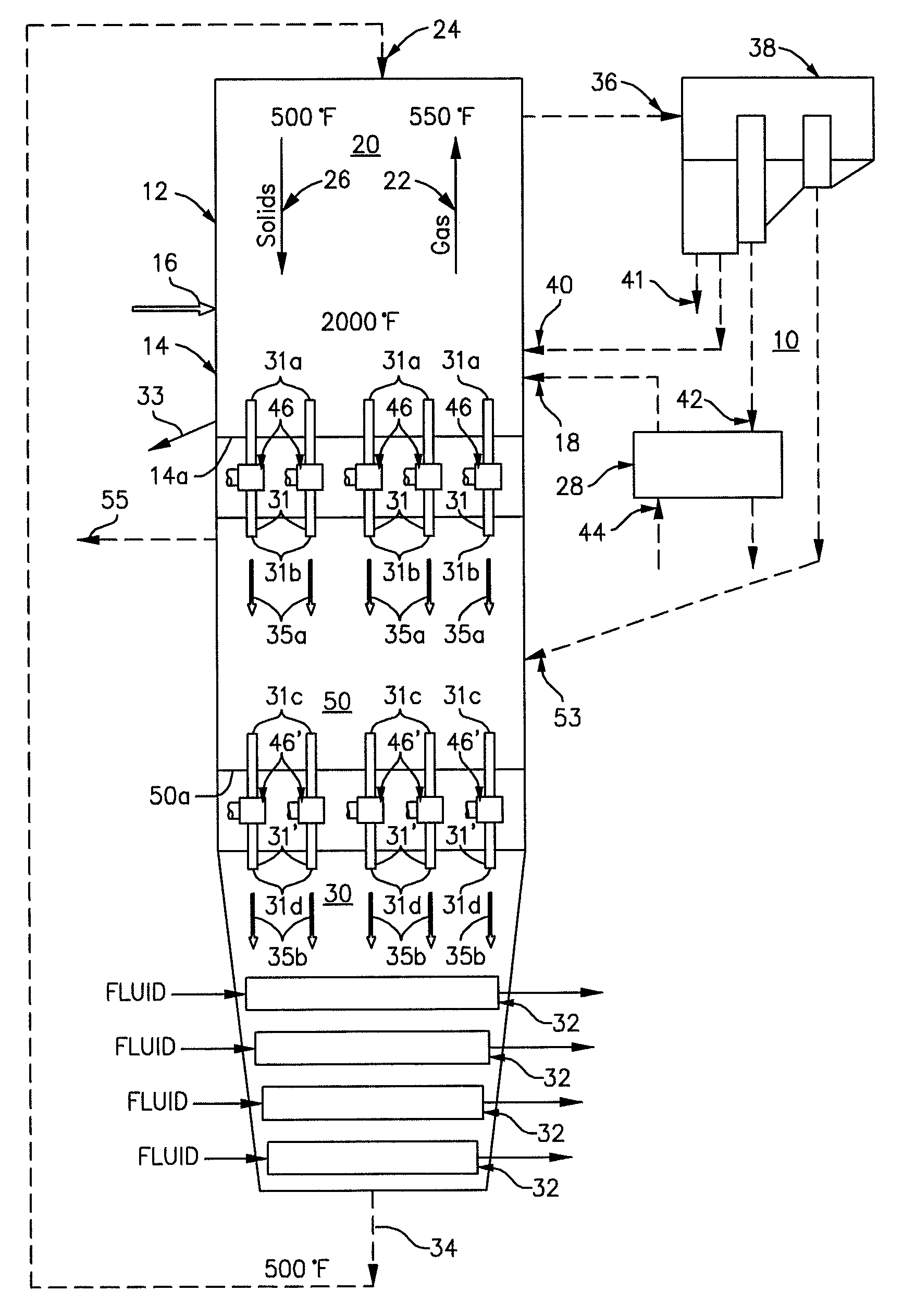
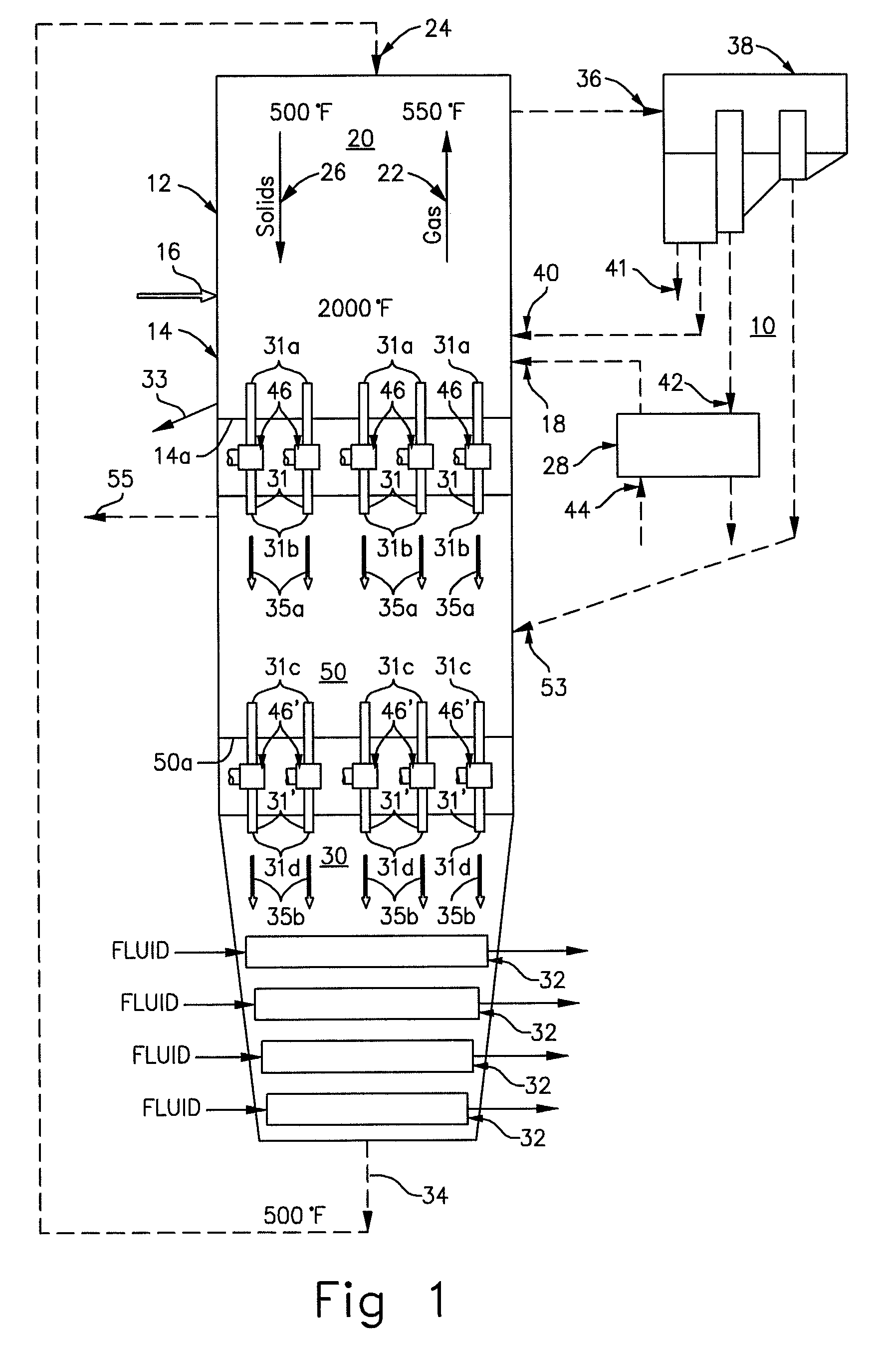
[0032]FIG. 1 depicts a heat transfer system, generally designated by the reference numeral 10, having an internally generated heat source. The heat transfer system 10 includes a first portion, i.e., a vessel 20 which is composed of two zones, i.e., a lower zone 14 and an upper zone 12. In the system 10 of FIG. 1, the lower zone 14 is operative as a combustion zone, i.e., as the zone in which the internally generated heat source is generated. For an internally generated heat source, fuel 16 and combustion air 18 are injected in the lower zone 14. The injected fuel 16 and combustion air 18 are combusted, preferably through the use of conventional bubbling bed technology, thereby producing hot gases 22, which typically include residual ash / sorbent particles, that undergo an upward flow. It will be understood that the system 10 could, if desired, be easily adapted by those of routine skill in the art to facilitate use of an externally generated heat source, in lieu of the depicted inter...
PUM
| Property | Measurement | Unit |
|---|---|---|
| Temperature | aaaaa | aaaaa |
| Temperature | aaaaa | aaaaa |
| Flow rate | aaaaa | aaaaa |
Abstract
Description
Claims
Application Information