Method for recycling exhaust gases from fischer-tropsch synthesis

Inactive Publication Date: 2015-05-07
WUHAN KAIDI ENG TECH RES INST CO LTD
View PDF2 Cites 0 Cited by
  • Summary
  • Abstract
  • Description
  • Claims
  • Application Information

AI Technical Summary

Benefits of technology

[0007]In view of the above-described problems, it is one objective of the invention to provide a method for recycling exhaust gas from Fischer-Tropsch synthesis. The method can transform par

Problems solved by technology

However, the inert gas in the raw gas tends to accumulate in the reactor, which adversely affects the production efficiency.
The syngas from the gasification of biomass or coal often has a low hydrogen-carbon ratio, which cannot meet the requirement of the Fischer-Tropsch synthesis.
However, the

Method used


Image

  • Method for recycling exhaust gases from fischer-tropsch synthesis
  • Method for recycling exhaust gases from fischer-tropsch synthesis
  • Method for recycling exhaust gases from fischer-tropsch synthesis

Examples


Example

Example 1

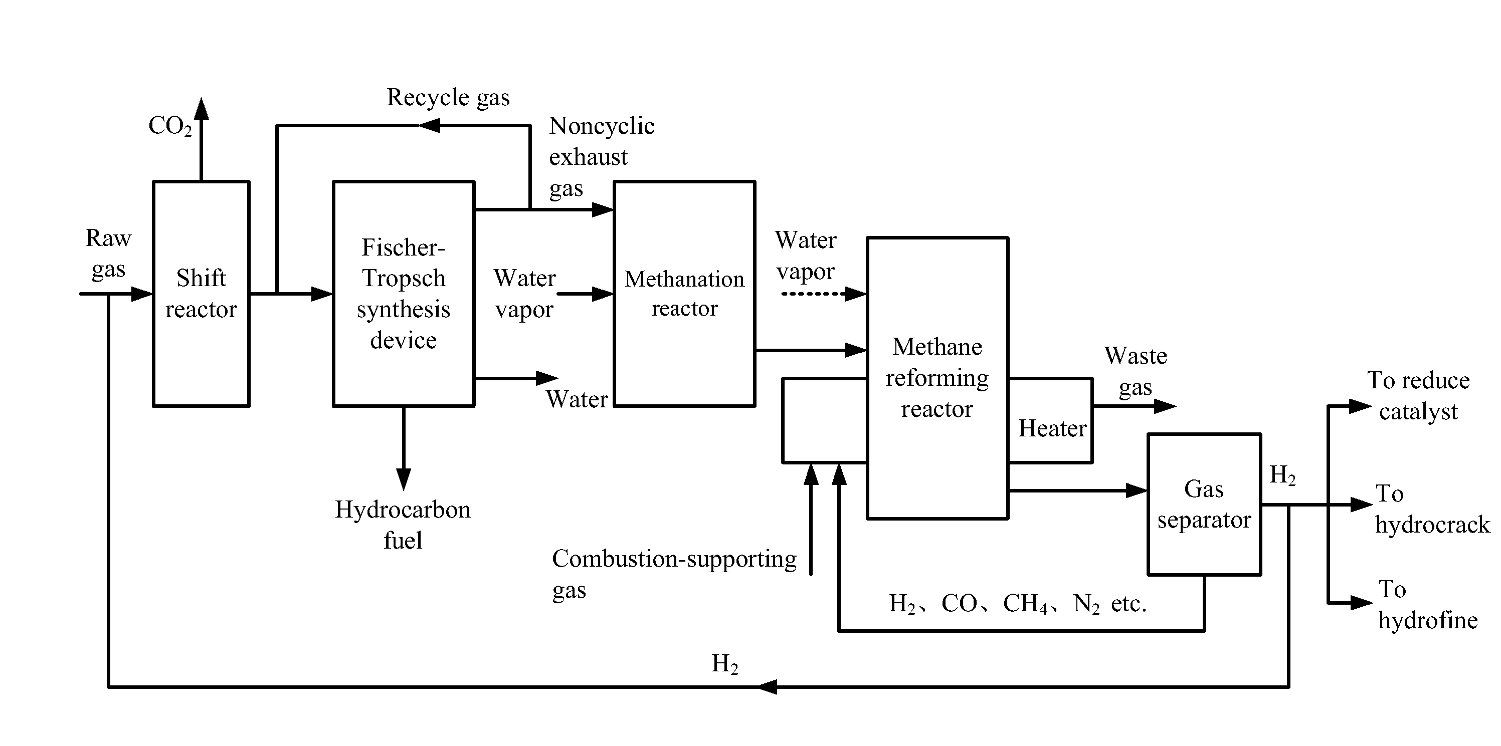
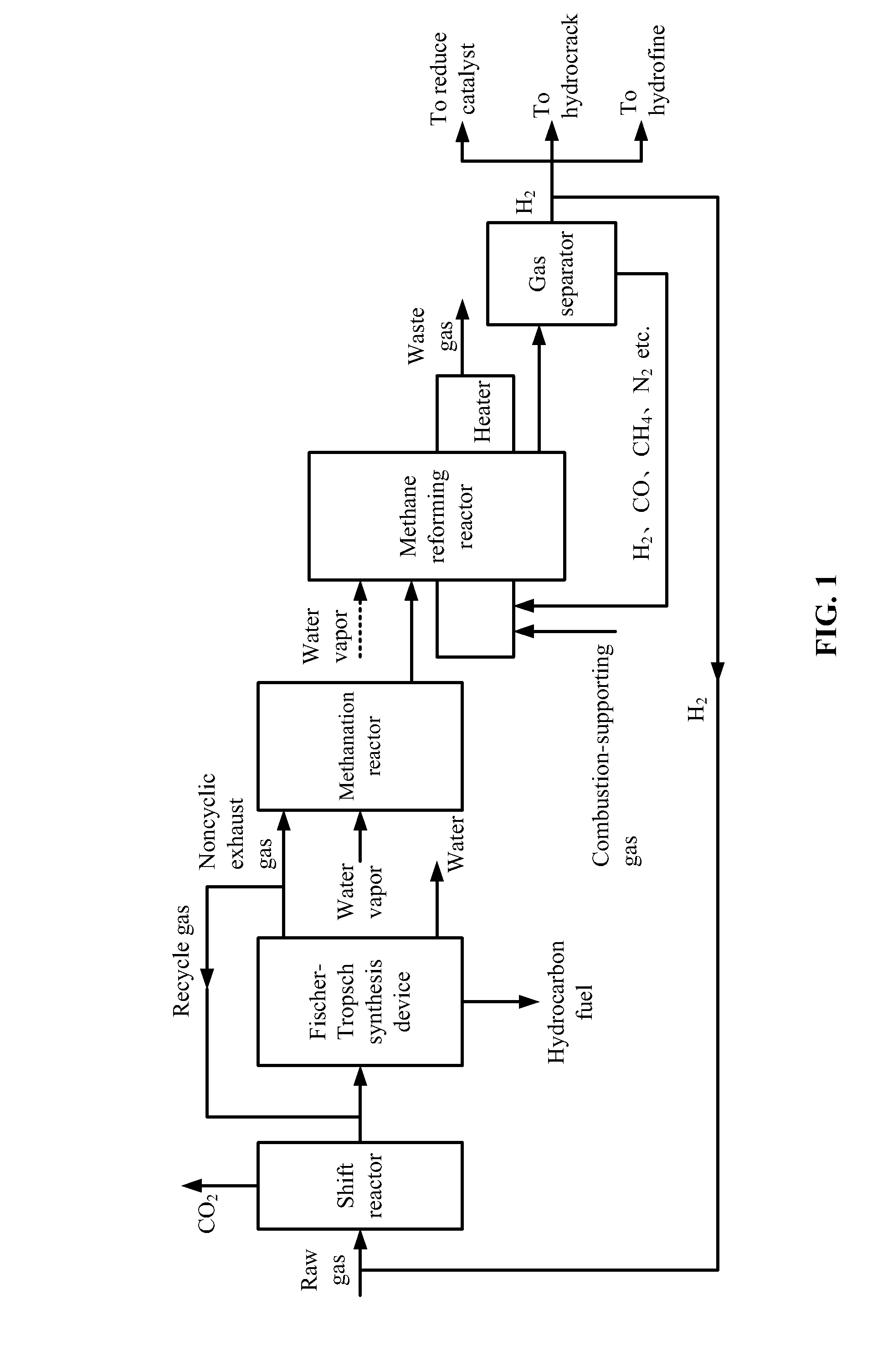
[0043]Raw gas involved in this example is the same as that in Comparison example, and the produced hydrogen is transported back to the shift reactor according to the flow chart in FIG. 1.

[0044]1) The raw gas was from the gasification of coal or biomass and comprised hydrogen and carbon monoxide with a molar ratio thereof of 0.1. The raw gas was introduced to a shift reactor at the flow rate of 5890 NM3 / h. A water-gas shift reaction between the hydrogen and the carbon monoxide was conducted at the temperature of 300° C. and the pressure of 2.0 MPa to yield hydrogen and carbon dioxide. After the reaction, 2120 NM3 / h of carbon monoxide was transformed into carbon dioxide, together with the generation of the same volume of hydrogen. Carbon dioxide was removed, and 4480 NM3 / h of shift gas was obtained. The molar ratio of hydrogen to carbon monoxide in the shift gas was 1.7, and the shift gas comprises more than 88% (v / v) of active components.

[0045]2) The shift gas was mixed with...

Example

Example 2

[0052]The treatment method of the exhaust gas in this example is the same as that in Example 1, and the produced hydrogen is transported back to the shift reactor according to the flow chart in FIG. 1.

[0053]1) The raw gas was from the gasification of coal or biomass and comprised hydrogen and carbon monoxide with a molar ratio thereof of 1.1. The raw gas was introduced to a shift reactor at the flow rate of 5950 NM3 / h. A water-gas shift reaction between the hydrogen and the carbon monoxide was conducted at the temperature of 200° C. and the pressure of 1.0 MPa to yield hydrogen and carbon dioxide. After the reaction, 256 NM3 / h of carbon monoxide was transformed into carbon dioxide, together with the generation of the same volume of hydrogen. Carbon dioxide was removed, and 4530 NM3 / h of shift gas was obtained. The molar ratio of hydrogen to carbon monoxide in the shift gas was 1.43, and the shift gas comprises more than 88% (v / v) of active components.

[0054]2) The shift gas ...

Example

Example 3

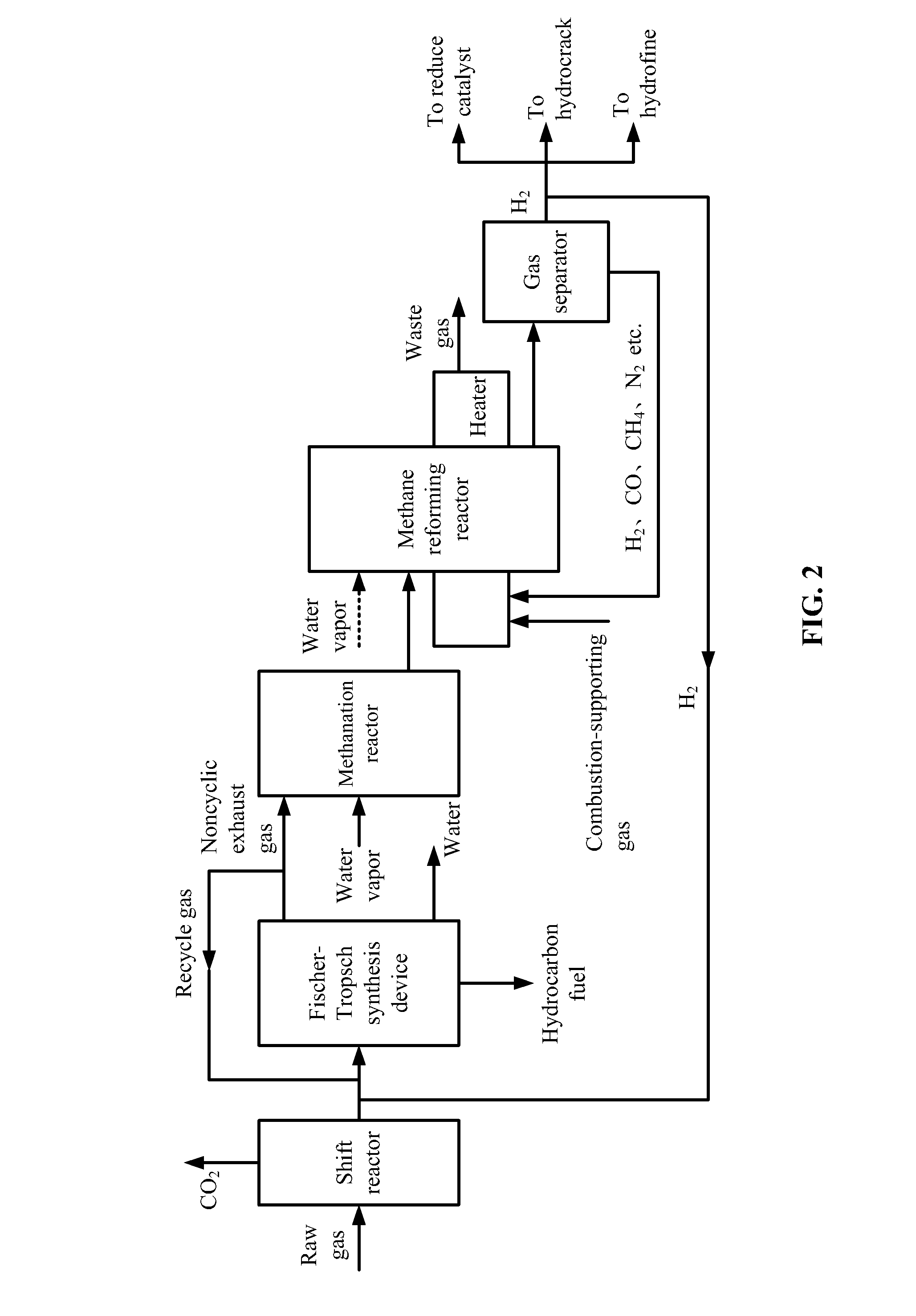
[0061]Raw gas involved in this example is listed in Table 4, and the produced hydrogen is transported back to the Fischer-Tropsch synthesis device according to the flow chart in FIG. 2.

[0062]1) The raw gas was from the gasification of coal or biomass and comprised hydrogen and carbon monoxide with a molar ratio thereof of 2.2. The raw gas was introduced to a shift reactor at the flow rate of 5900 NM3 / h. A water-gas shift reaction between the hydrogen and the carbon monoxide was conducted at the temperature of 500° C. and the pressure of 4.0 MPa to yield hydrogen and carbon dioxide. After the reaction, 300 NM3 / h of carbon monoxide was transformed into carbon dioxide, together with the generation of the same volume of hydrogen. Carbon dioxide was removed, and 5090 NM3 / h of shift gas was obtained. The molar ratio of hydrogen to carbon monoxide in the shift gas was 3.0, and the shift gas comprises more than 95% (v / v) of active components.

[0063]2) The shift gas was mixed with 10...


PUM

PropertyMeasurementUnit
Temperatureaaaaaaaaaa

Abstract

A method for recycling exhaust gas from Fischer-Tropsch synthesis. The method includes: 1) introducing raw gas to a shift reactor to conduct a water-gas shift reaction, and collecting shift gas; 2) introducing the shift gas to a Fischer-Tropsch synthesis device to yield a hydrocarbon fuel and exhaust gas, returning part of the exhaust gas as recycle gas; 3) introducing another part of the exhaust gas to a methanation reactor, allowing a methanation reaction to happen between the part of the exhaust gas and water vapor; 4) introducing a mixed gas product from the methanation reaction to a methane reforming reactor; 5) transporting the hydrogen and carbon monoxide resulting from the methane reforming reaction to a gas separator, separating the hydrogen and obtaining a mixed gas including carbon dioxide; and 6) returning the mixed gas including carbon dioxide to the methane reforming reactor.

Description

CROSS-REFERENCE TO RELATED APPLICATIONS[0001]This application is a continuation-in-part of International Patent Application No. PCT / CN2013 / 079219 with an international filing date of Jul. 11, 2013, designating the United States, now pending, and further claims priority benefits to Chinese Patent Application No. 201210246633.1 filed Jul. 17, 2012. The contents of all of the aforementioned applications, including any intervening amendments thereto, are incorporated herein by reference. Inquiries from the public to applicants or assignees concerning this document or the related applications should be directed to: Matthias Scholl P. C., Attn.: Dr. Matthias Scholl Esq., 245 First Street, 18th Floor, Cambridge, Mass. 02142.BACKGROUND OF THE INVENTION[0002]1. Field of the Invention[0003]The invention relates to a process for recycling exhaust gases from Fischer-Tropsch synthesis, thereby reducing carbon emissions.[0004]2. Description of the Related Art[0005]Typically, to improve the effici...

Claims


Application Information

Patent Timeline
IPC IPC(8): C01B3/16C07C4/06C07C1/04
CPCC10G2/00C01B3/16C07C1/0485C07C4/06C07C2523/755C01B2203/062C01B2203/1241C01B2203/84C01B2203/0283C01B3/34C01B2203/0233C01B2203/04C01B2203/0445C01B2203/047C01B2203/0475C01B2203/0805C01B2203/0827C10G2/30C10G2/332C10K1/005C10K3/04C10K3/06C01B3/38C01B2203/142Y02P20/10
Inventor CHEN, YILONGKUAI, PINGYUGONG, YANZHAN, XIAODONGZHANG, YANFENGJIN, JIAQI
Owner WUHAN KAIDI ENG TECH RES INST CO LTD
Why Eureka
Try Eureka