
Electrostatic Atomizer

a technology of atomizer and atomizer, which is applied in the direction of electrostatic heating/cooling, electrostatic spraying apparatus, burners, etc., to achieve the effect of saving water supply trouble and stably generating high voltag

Inactive Publication Date: 2009-08-20
MATSUSHITA ELECTRIC WORKS LTD
View PDF2 Cites 14 Cited by
  • Summary
  • Abstract
  • Description
  • Claims
  • Application Information

AI Technical Summary

Benefits of technology

[0005]It is therefore an object of the present invention to stably generate high voltage for forming mist of charged fine particles in the order of nanometer in size in addition to saving the trouble of supplying water.
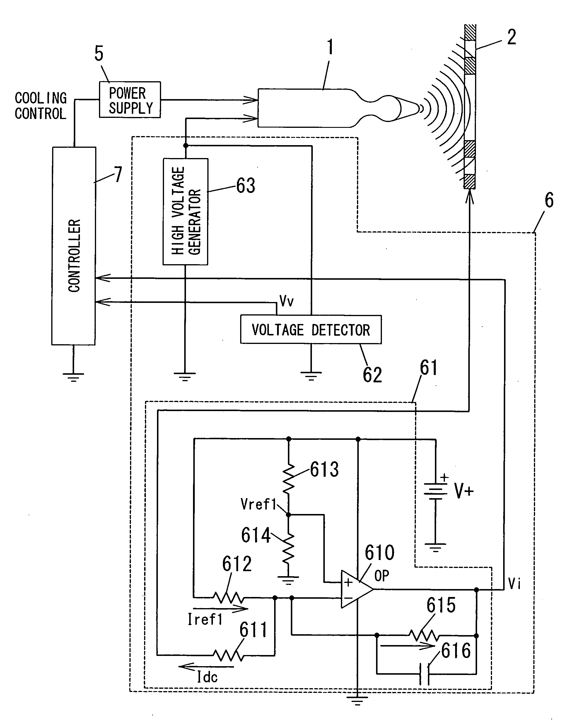
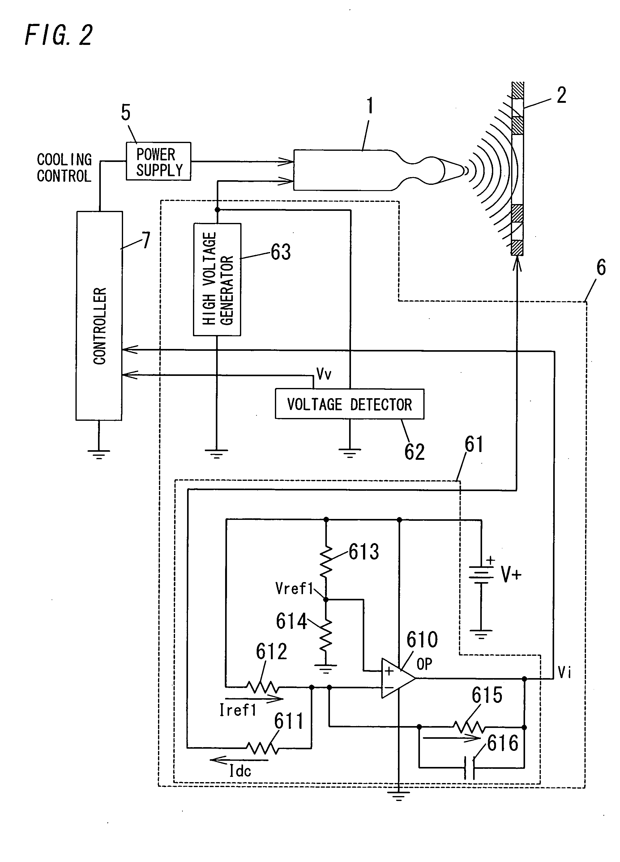
[0006]An electrostatic atomizer of the present invention comprises a discharge electrode, a counter electrode located opposite the discharge electrode, a cooling source that cools the discharge electrode to form thereon dew as water, a high voltage power supply that applies high voltage for discharge across the electrodes, and a voltage detector that detects voltage between the electrodes. The power supply includes a control device and a voltage stabilizing device that are opposite to each other in temperature characteristic. The control device is configured to pick up the voltage detected with the detector via the voltage stabilizing device, and to adjust the high voltage applied across the electrodes through feedback control so that the voltage corresponds to specified discharge voltage. In this configuration, the discharge voltage between the electrodes is stabilized to the specified discharge voltage. Therefore, even under unstable temperature conditions, it is possible to stably generate high voltage for forming mist of charged fine particles in the order of nanometer in size.
[0007]Preferably, the atomizer further comprises a current detector that detects a current flowing between the electrodes, and a controller that adjusts a cooling rate of the cooling source based on a value of a predetermined specified current. The controller raises the rate when a value of the current detected with the current detector is smaller than the value of the specified current, and lowers the rate when the value of the current is larger than the value of the specified current. In this configuration, it is possible to suitably adjust quantity of the dew formed on the discharge electrode.

Problems solved by technology

However, the prior art device requires that water is supplied into the cartridge.

Method used


Image

  • Electrostatic Atomizer
  • Electrostatic Atomizer
  • Electrostatic Atomizer

Examples


Embodiment Construction

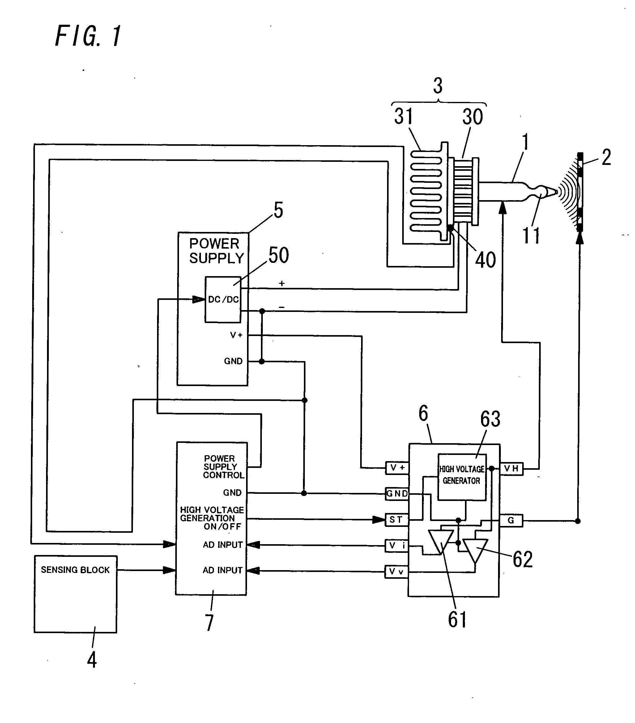
[0021]FIG. 1 shows an embodiment according to the present invention (i.e., electrostatic atomizer). This electrostatic atomizer comprises a discharge electrode 1, a counter electrode 2, a cooling source 3, a sensing block 4, a DC power supply 5, a high voltage power supply 6 and a controller 7.

[0022]The discharge electrode 1 has a teardrop-shaped tip 11, and receives negative or positive high voltage (e.g., −4.6 kV) from the high voltage power supply 6 when it is discharged. The counter electrode 2 is formed into a ring shape of which inner edge functions as a substantial electrode, and is located opposite the tip 11 of the electrode 1 a given distance apart. The electrode 2 is also connected with ground.

[0023]The cooling source 3 is formed of, for example, a Peltier module 30 and a heat-radiating fin 31, and cools the discharge electrode 1 to a temperature lower than a dew point temperature of ambient air to form thereon dew as water. A base of the electrode 1 is connected with the...


PUM


Abstract

An electrostatic atomizer comprising a discharge electrode, a counter electrode, a cooling source, a high voltage power supply and a voltage detector. The cooling source cools the discharge electrode to form thereon dew as water. The power supply applies high voltage for discharge across the electrodes. The detector detects voltage between the electrodes. The power supply includes a control device and a voltage stabilizing device that are opposite to each other in temperature characteristic. The control device operates to pick up the voltage detected with the detector via the voltage stabilizing device, and to adjust the high voltage applied across the electrodes through feedback control so that the voltage corresponds to specified discharge voltage.

Description

TECHNICAL FIELD[0001]The invention relates generally to electrostatic atomizers and more particularly to an electrostatic atomizer that generates mist of charged fine particles in the order of nanometer in size.BACKGROUND ART[0002]Such sort of electrostatic atomizer is seen in, for example, the patent document of Japanese Patent Number 3260150 (European Patent Publication Number 0 486 198 A1 or U.S. Pat. No. 5,337,963). A prior art device described in the document comprises a cartridge for storage of liquid suitable for electrostatic spraying, and a high voltage means for applying electrostatic potential to the liquid. The cartridge includes a capillary structure that extends into the interior of the cartridge so as to feed liquid by capillary action from the cartridge to a spraying outlet at a tip of the capillary structure. The cartridge also includes a means for providing an electrically conductive path to allow the application of an electrostatic charge to the liquid. When the h...

Claims


Application Information

Patent Timeline
IPC IPC(8): B05B5/057B05B5/053
CPCB05B5/001B05B5/10B05B5/057
Inventor AKISADA, SHOUSUKEHIRAI, TOSHIHISAHIRAI, KISHIKOWADA, SUMIOMATSUMOTO, TATSUHIKO
Owner MATSUSHITA ELECTRIC WORKS LTD
Learn More