Lever Drive Wheelchair Transmission

a wheelchair and transmission technology, applied in the direction of wheelchair/patient transportation, transportation and packaging, gearing, etc., can solve the problems of limiting the general acceptance of potential users, affecting the safety of wheelchair users, so as to achieve less angular excursion

Inactive Publication Date: 2009-08-20
GREEN STEVE C
View PDF15 Cites 21 Cited by
  • Summary
  • Abstract
  • Description
  • Claims
  • Application Information

AI Technical Summary

Benefits of technology

[0011]The present invention improves on the state of the art by providing a lever propulsion means for manual wheelchairs that allows directional control shifting, forward / reverse and reverse / forward, with operator directional control input through the rotation of the propulsion lever handgrip of less angular excursion than previously utilized. This small angle direction shifting allows the operator to maintain a non-changing hand grip position such that propulsion movement of the levers may be comfortably simultaneous with direction shifting.OBJECTS OF THE INVENTION
[0015]A further object of this invention is to provide an ergonomically and operationally improved method of selecting the direction of lever drive wheelchair propulsion.
[0017]A further object of the invention is to provide a reversible one-way roller clutch system that provides a neutral position in which the clutch input and output elements can freewheel with respect to each other in either direction of rotation.
[0018]Another object of the invention is to provide a shifter over-travel compensation means that will protect the one-way clutch shifting mechanism from damage by shift motions of excessive excursion and force.
[0019]Another object of the invention is provide a means by which a user of the invention can change the relative sense of the transmission rotation by means of the same hand grip that is used to impart propelling motion to the lever.
[0020]Another object of the invention is to provide a reversible one-way clutch of less complexity and cost to manufacture than the current state of the art.

Problems solved by technology

To this point in tile state of the art, lever drive mechanisms have all had deficiencies that limit general acceptance by potential users.
These deficiencies include being too heavy, too bulky, having non-ergonomic forward / reverse shifting control inputs, and being obtrusive in appearance.
This style of lever drive is exceptionally obtrusive in appearance, needlessly heavy, and has not been accepted by the user community.
Although potentially less obtrusive than the forward mount lever arrangement discussed above, the bulky physical size of current hub mount lever drive mechanisms causes them to be placed on the outside of the driving wheel, and thus still objectionably obvious.
Additionally, this placement causes the width of the wheelchair to increase, which is problematic for passing through typical doorways.
This results in an awkwardly large angle through which the user must rotate the handgrip in order to affect change of direction, forvard / reverse or reverse / forward shifts.
This condition significantly impairs the user experience, and predisposes users to forego using a lever drive wheelchair, other benefits notwithstanding.
This results in an expensive clutch and control arrangement, not well suited to low production uses such as wheelchairs.
Various roller clutch mechanisms are known to the art, but fail to adequately address wheelchair lever drive needs.
This type of clutch is complex and problematically expensive to manufacture in small quantities for wheelchair applications.
Due to the dependence on individual springs for roller biasing, the arrangement thus taught is limited to a bi-state operation, as the springs will push the rollers either one direction on the other, and are not intended or able to achieve an intermediate position.
This arrangement as presented is of greater complexity and cost than is needed for wheelchair transmissions.
However, the specific needs of manual wheelchair propulsion by lever drive present challenges not adequately addressed by the state of the art.

Method used


Image

  • Lever Drive Wheelchair Transmission
  • Lever Drive Wheelchair Transmission
  • Lever Drive Wheelchair Transmission

Examples


Embodiment Construction

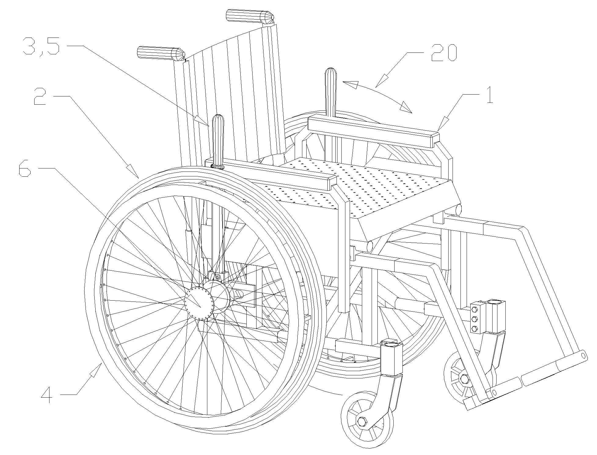
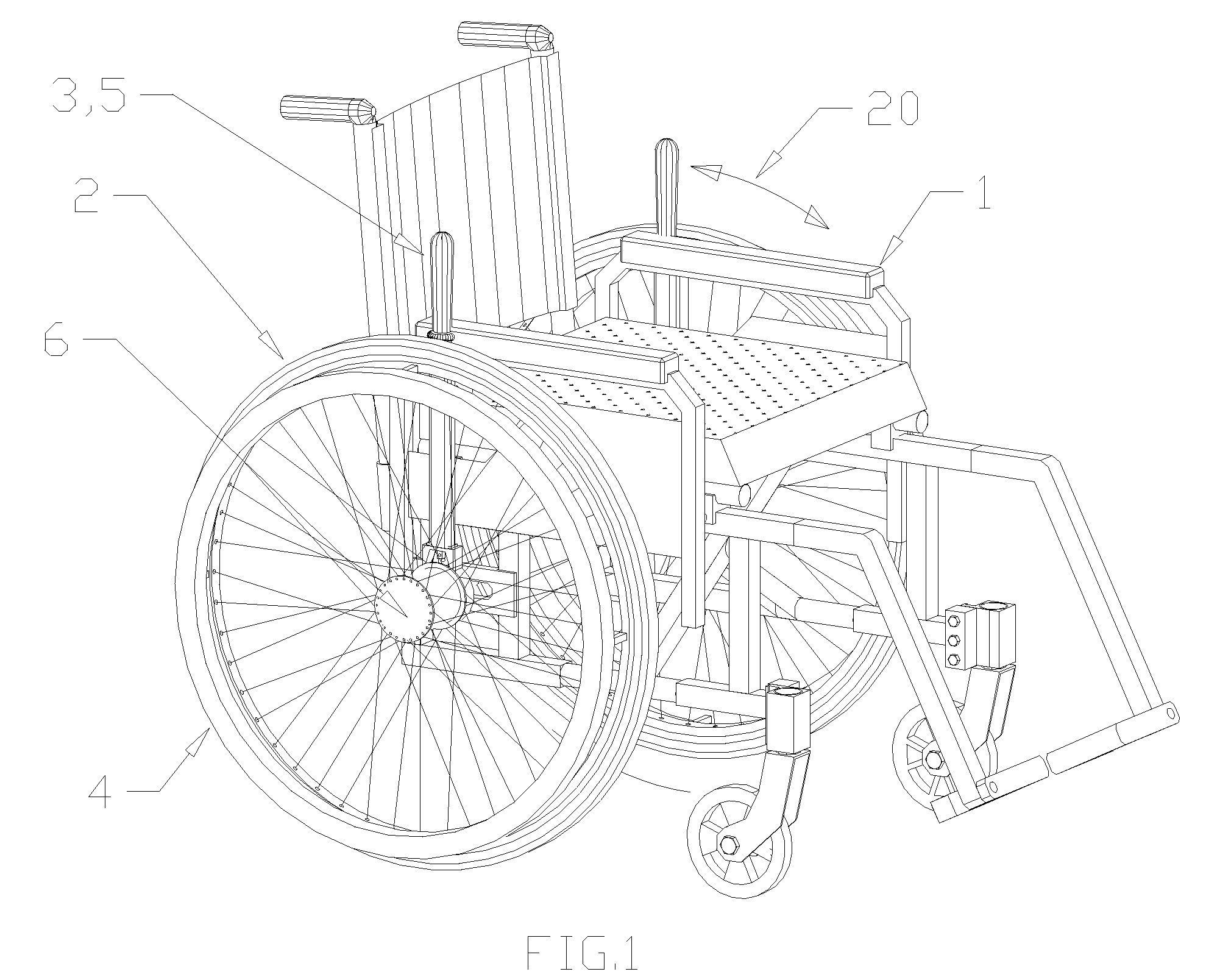
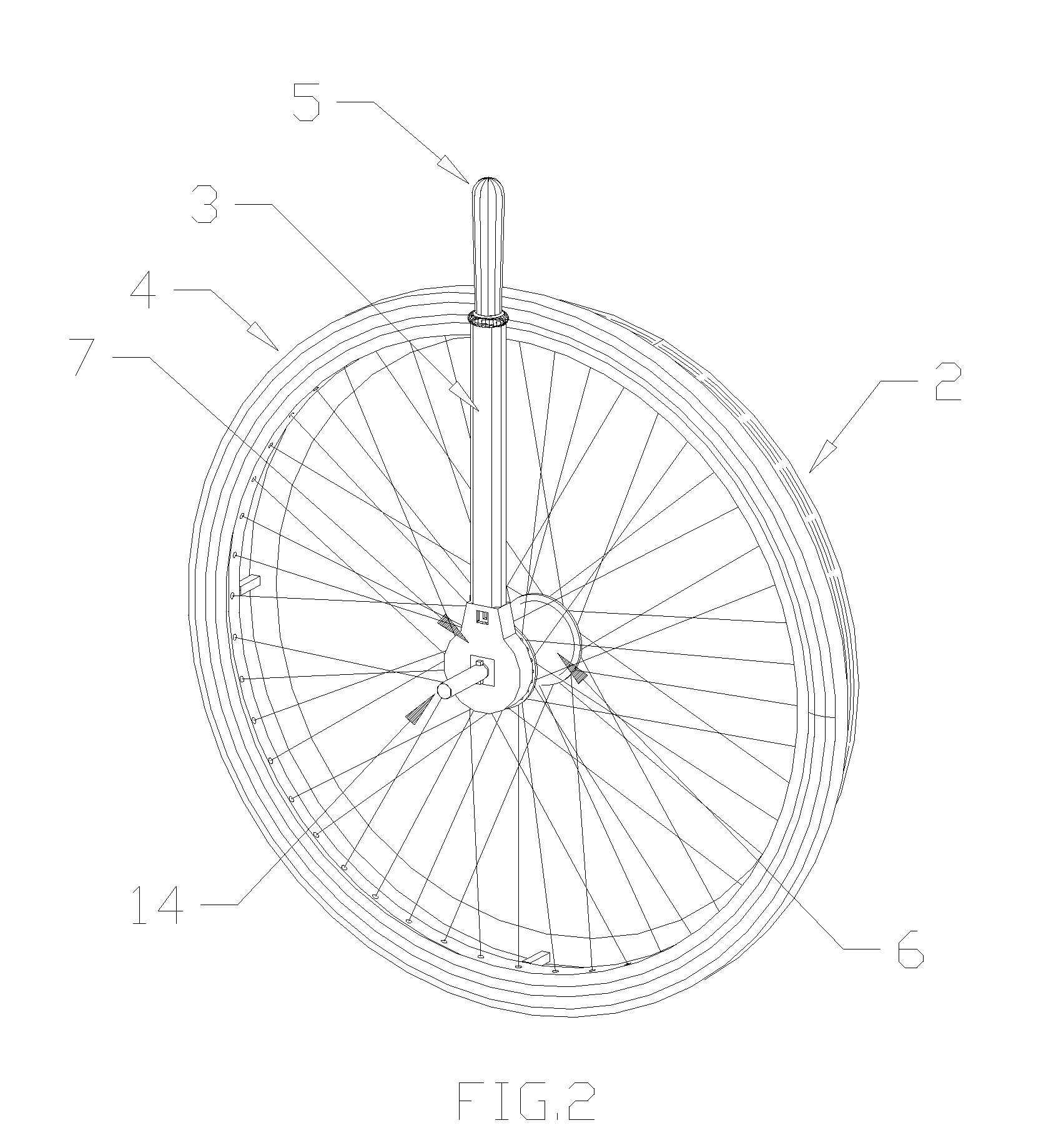
[0027]With reference to FIGS. 1 through 6, a typical wheelchair 1 is shown with a preferred embodiment of the lever drive wheelchair transmission installed on the wheelchair frame. It can be seen that propulsion levers 3 and associated hand grips 5 are placed to the inside of rear drive wheels 2. This position is preferable to outside placement as it allows handgrips 5 to be closer together side-to-side in an ergonomically advantageous position, and, unique to this invention, does increase the overall width of the wheelchair. It also makes the overall lever drive mechanism aesthetically less obtrusive, a feature shown by independent survey to be important to users. Lever motion arrows 20 indicate the approximate arc of reciprocating motion that the user would impart to levers 20 when propelling chair 1.

[0028]When propelling wheelchair 1 a user would (,rasp grip 5 and push or pull., thus imparting a propelling motion shown by arrow 20, and could, as desired, impact a directional shif...


PUM


Abstract

A manual propulsion mechanism for wheelchairs utilizes a lever pivotally mounted to the hub of each rear wheel such that the wheelchair user can propel the chair with push / pull movements of the levers. Forward and reverse propulsion directions are accomplished by a system of one-way reversible clutches contained in the propulsion wheel hubs which also allow the levers to be operationally disconnected such that the chair can freewheel. Operator control of direction shifting is through twisting motions imparted to the grip handles of the propulsion levers. In a preferred embodiment, improved ergonomics for propulsion direction changes are made possible by an improved short excursion clutch shifting mechanism that reduces the angle of arc through which the operator must twist the grip handle to effect the direction change. This allows the operator to retain a comfortable, stable grip on the grip handle while simultaneously propelling and controlling direction of movement.

Description

CROSS-REFERENCE TO RELATED APPLICATIONS [0001]Not applicableSTATEMENT REGARDING FEDERALLY SPONSORED R&D [0002]Not applicableREFERENCE TO SEQUENCE LISTING OR COMPUTER PROGRAM [0003]Not applicableBACKGROUND OF THE INVENTION[0004]Wheelchairs are typically intended to allow the user to move about without the use of their legs, and provide means of allowing arm movement to cause rotation of one or more wheels of the wheelchair. In the commonest and simplest form, round pushrims of slightly smaller diameter than the propelling wheels are fixed to the said propelling wheels, such that the user may conveniently grasp the pushrims to exert a rotational torque to the driving wheels through the pushrims. Although such means of propelling is simple, light in weight, and inexpensive, problems with pushrims include placing the users hand near the tires of the driving wheels which may be dirty, requiring considerable grip strength to grasp the pushrim, and repetitive motion injuries from the non-o...

Claims


Application Information

Patent Timeline
Patent Type & Authority Applications(United States)
IPC IPC(8): B62M1/16F16H27/02
CPCA61G5/023A61G5/025Y10T74/1555F16H31/002B62M1/16
Inventor GREEN, STEVE C.
Owner GREEN STEVE C
Why Eureka
Try Eureka