Starter solenoid switch with improved arrangement of resistor

a solenoid switch and resistor technology, applied in the direction of engine starters, machines/engines, relays, etc., can solve the problems of excessive temperature difficult to dissipate heat generated by the solenoid coil in the radially outward direction, shortening the thermal withstand time of the solenoid coil,

Inactive Publication Date: 2009-08-20
DENSO CORP
View PDF9 Cites 30 Cited by
  • Summary
  • Abstract
  • Description
  • Claims
  • Application Information

AI Technical Summary

Benefits of technology

[0018]The solenoid switch further includes a cup-shaped case that has first and second portions. The first portion includes a closed end of the case and has the solenoid coil received the

Problems solved by technology

Further, since the radially outer periphery of the solenoid coil is surrounded by the retainer via the resistor, it is difficult to dissipate heat generated by the solenoid coil in the radially outward direction.
As a result, the tempe

Method used


Image

  • Starter solenoid switch with improved arrangement of resistor
  • Starter solenoid switch with improved arrangement of resistor
  • Starter solenoid switch with improved arrangement of resistor

Examples


first embodiment

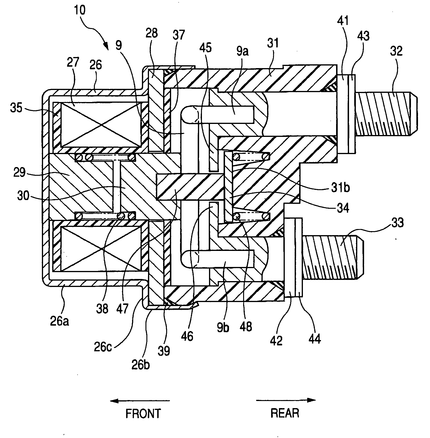
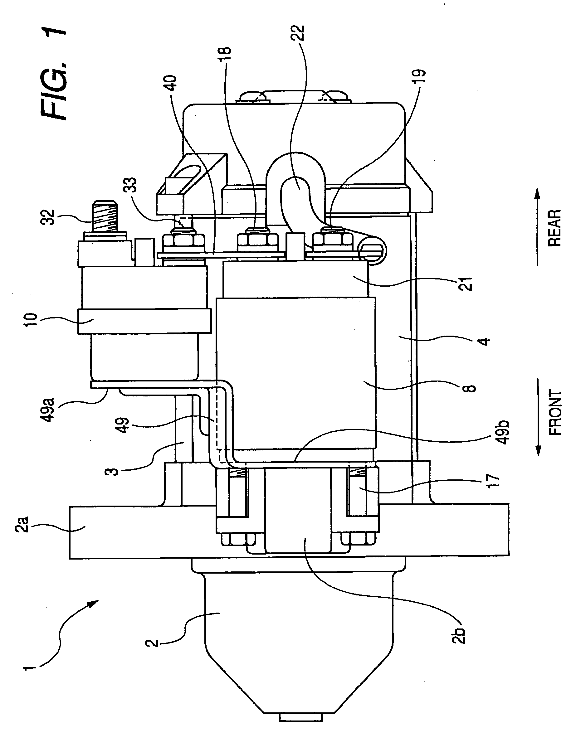
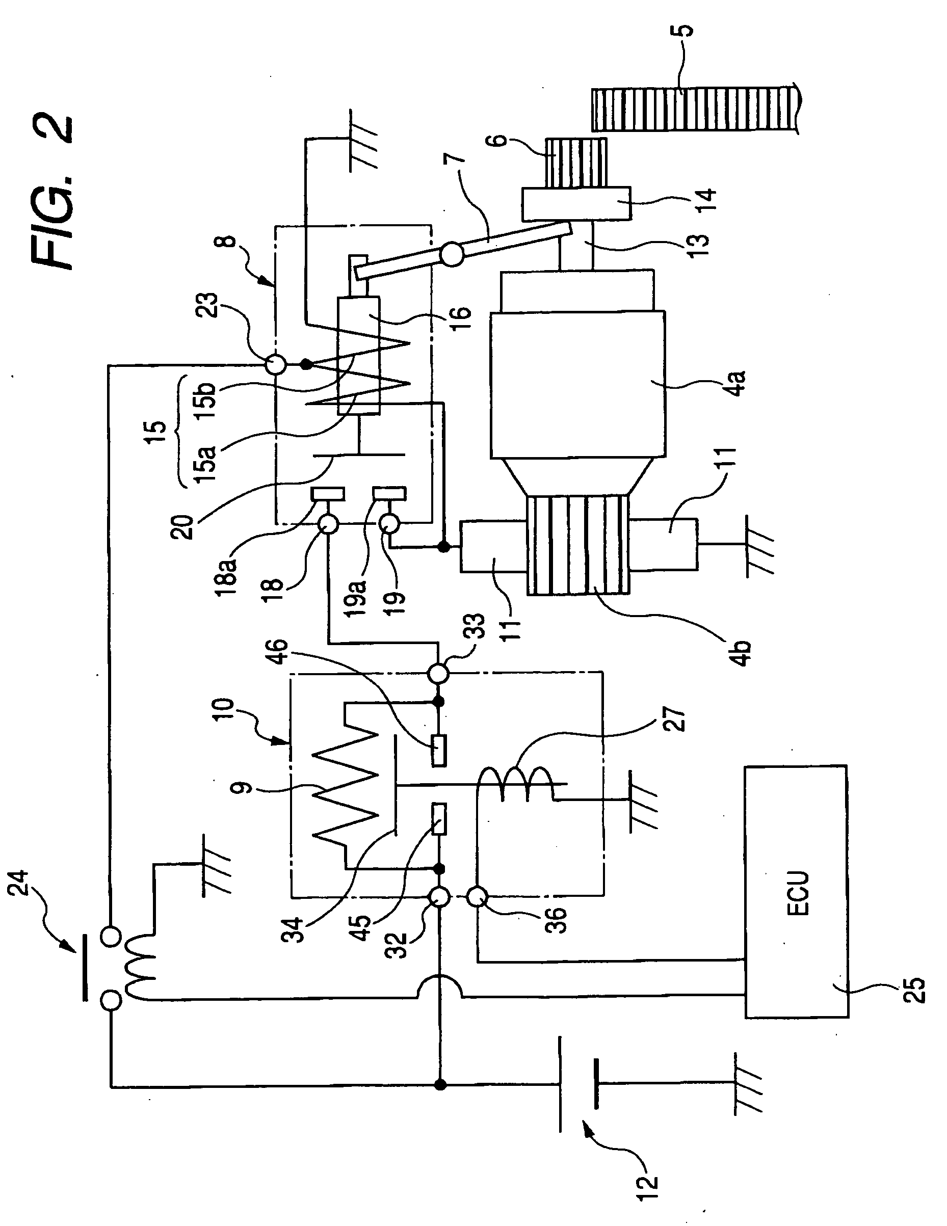
[0036]FIG. 1 shows the overall structure of a starter 1 for starting an internal combustion engine of a motor vehicle, which includes a solenoid switch 10 according to the first embodiment of the invention. FIG. 2 shows an electric circuit of the starter 1.

[0037]The starter 1 includes: a housing 2 that is mounted to the engine (not shown); a motor 4 that is fixed to the housing 2 by means of a plurality of through-bolts 3; a pinion 6 (shown in FIG. 2) that is configured to mesh with a ring gear 5 (shown in FIG. 2) of the engine to transmit the torque generated by the motor 4 to the engine; a shift lever 7 (shown in FIG. 2) that is configured to shift the pinion 6 in the axial direction of the starter 1 to bring the pinion 6 into and out of mesh with the ring gear 5; a solenoid switch 8 that serves as a main switch of starter 1; a resistor 9 for limiting electric current supplied from a battery 12 to the motor 4 during a starting operation; and the solenoid switch 10 according to the...

second embodiment

[0092]This embodiment illustrates a method of joining the resistor 9 to the terminal bolts 32 and 33.

[0093]Referring to FIG. 6, in the present embodiment, the terminal bolt 32 has a bore 32a that opens on the front end face of the terminal bolt 32 and has a predetermined depth. The terminal bolt 32 also has two recesses 32b that are formed in the side surface of the terminal bolt 32 and opposed to each other in the radial direction of the terminal bolt 32 with the bore 32a interposed therebetween. Similarly, the terminal bolt 33 has a bore 33a that opens on the front end face of the terminal bolt 33 and has a predetermined depth. The terminal bolt 33 also has two recesses 33b that are formed in the side surface of the terminal bolt 33 and opposed to each other in the radial direction of the terminal bolt 33 with the bore 33a interposed therebetween. It should be noted that in FIG. 6, the forward and backward directions are introduced only for convenience of explanation.

[0094]The fir...

third embodiment

[0101]This embodiment illustrates anther method of joining the resistor 9 to the terminal bolts 32 and 33.

[0102]Referring to FIG. 7, in the present embodiment, the terminal bolt 32 has a protrusion 32c that protrudes from the front end face of the terminal bolt 32 to have a predetermined protruding height from the front end face. Further, as shown in FIG. 8, the protrusion 32c has a rectangular bottom and tapers toward its top to have a trapezoidal cross section. Similarly, the terminal bolt 33 has a protrusion 33c that protrudes from the front end face of the terminal bolt 33 to have the predetermined protruding height from the front end face. Further, as shown in FIG. 8, the protrusion 33c has a rectangular bottom and tapers toward its top to have a trapezoidal cross section.

[0103]The first and second ends 9a and 9b of the resistor 9 are respectively disposed on the tops of the protrusions 32c and 33c of the terminal bolts 32 and 33, and respectively joined to the tops of the prot...


PUM


Abstract

In a solenoid switch according to the invention, a magnetic plate is disposed on one side of a solenoid coil in an axial direction of the solenoid coil. A contact cover is arranged with the magnetic plate interposed between the contact cover and the solenoid coil in the axial direction. First and second fixed contacts are received in the contact cover and respectively electrically connected to first and second terminals that are to be electrically connected to an electric circuit. A resistor is electrically connected between the first and second terminals to limit current flowing through the electric circuit when the first and second fixed contacts are electrically disconnected by a movable contact. The resistor is received in the contact cover and interposed between the magnetic plate and the first and second fixed contacts in the axial direction.

Description

CROSS-REFERENCE TO RELATED APPLICATIONS[0001]This application claims priority from Japanese Patent Applications No. 2008-39233, filed on Feb. 20, 2008, and No. 2008-325261, filed on Dec. 22, 2008, the contents of which are hereby incorporated by reference into this application.BACKGROUND OF THE INVENTION[0002]1. Technical Field of the Invention[0003]The present invention relates generally to solenoid switches (or electromagnetic switches) for controlling power supply to starter motors. More particularly, the invention relates to a solenoid switch which has an improved arrangement of a resistor that is used to limit electric current supplied to a starter motor.[0004]2. Description of the Related Art[0005]Japanese Patent No. 3767550, an English equivalent of which is U.S. Pat. No. 6,923,152 B2, discloses a starter for starting an internal combustion engine which includes a motor and a solenoid switch for driving the motor in two stages.[0006]More specifically, the solenoid switch incl...

Claims


Application Information

Patent Timeline
IPC IPC(8): H01F7/06
CPCF02N11/087F02N15/067H01H51/065H01H50/54F02N2250/02F02N11/08F02N11/00H01H50/04H01H50/44
Inventor NIIMI, MASAMI
Owner DENSO CORP
Why Eureka
Try Eureka