Connector and radio frequency apparatus

a radio frequency apparatus and connector technology, applied in the field of machines, can solve the problems of unnecessary space and support, and achieve the effects of reducing installation costs, reducing signal transmission losses, and reducing distance between antenna and rru

Inactive Publication Date: 2009-08-20
HUAWEI TECH CO LTD
View PDF9 Cites 26 Cited by
  • Summary
  • Abstract
  • Description
  • Claims
  • Application Information

AI Technical Summary

Benefits of technology

[0010]The connector adapted to fix the antenna has a clamping slot adapted to fix the RRU so that the antenna and the RRU are fixed to the connector. This makes it unnecessary to provide additional spaces and supports for installing the RRU. Hence, the RRU can be installed in a pr

Problems solved by technology

This makes it unnecessary to provide addition

Method used


Image

  • Connector and radio frequency apparatus
  • Connector and radio frequency apparatus
  • Connector and radio frequency apparatus

Examples


first embodiment

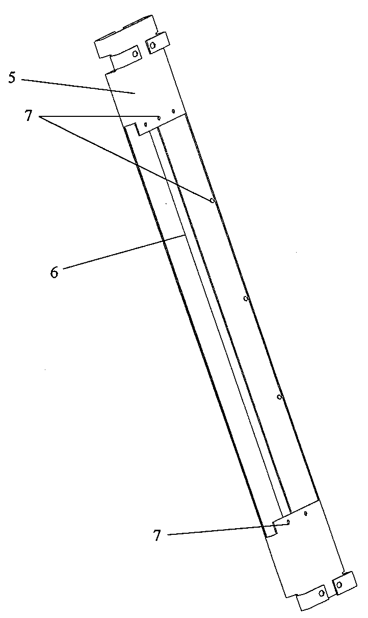
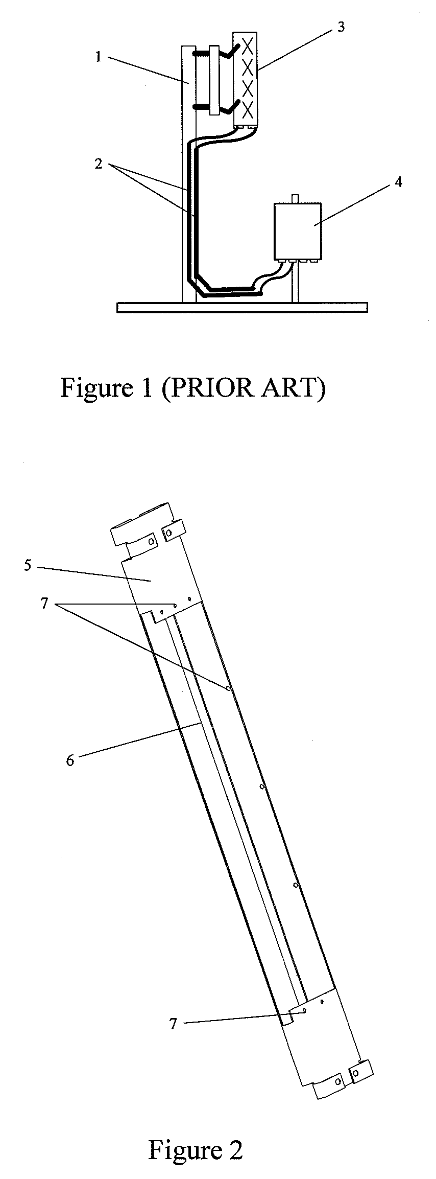
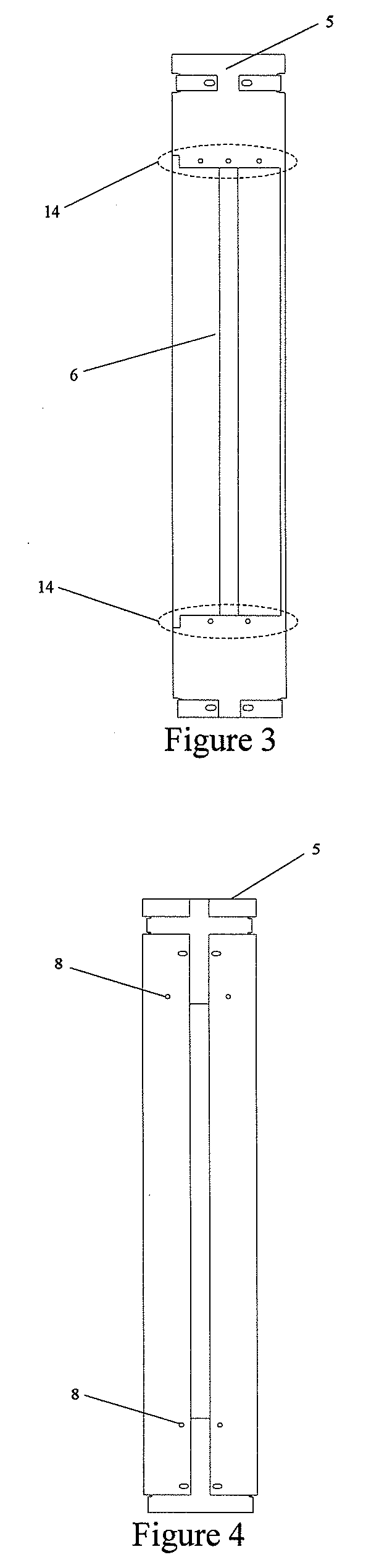
[0033]FIG. 8 shows the installation of the RRU and the connector in the present disclosure. As shown in FIG. 8, the RRU 4 may be pushed into the clamping slot 6 of the connector 5 from the side of the connector 5 so that the RRU 4 is clamped in the clamping slot 6 and fixed to the connector 5. To fasten the connection between the RRU 4 and the connector 5, an RRU tight side 15 may be set on the RRU 4, and a clamping slot tight side 14 may be set on the connector 5. In this case, when the RRU 4 is located in the clamping slot 6, the RRU tight side 15 can be located in the clamping slot 6 and the RRU tight side 15 presses the clamping slot tight side 14, ensuring that the RRU 4 is fixed to the connector 5.

[0034]The RRU fastening hole 7 may also be set on the clamping slot tight side 14 (see FIG. 2), and the screw may be tightened to the RRU tight side 15 through the RRU fastening hole 7 so as to fasten the connection between the RRU 4 and the connector 5.

[0035]In addition, the connect...

second embodiment

[0038]FIG. 10 shows the installation of the RRU and the connector in the present disclosure. As shown in FIG. 10, the RRU 4 may be pushed into the clamping slot 6 of the connector 5 from the bottom of the connector 5 so that the RRU 4 is clamped in the clamping slot 6 and fixed to the connector 5.

[0039]FIG. 11 shows a perspective view of the RRU and the connector that are installed according to FIG. 10. The RRU 4 and the connector 5 can be connected according to the installation mode shown in FIG. 10.

third embodiment

[0040]FIG. 12 shows the installation of the RRU and the connector in the present disclosure. As shown in FIG. 12, the RRU 4 may be pushed into the clamping slot 6 of the connector 5 from the top of the connector 5 so that the RRU 4 is clamped in the clamping slot 6 and fixed to the connector 5.

[0041]FIG. 13 shows a perspective view of the RRU and the connector that are installed according to FIG. 12. As shown in FIG. 13, the RRU 4 and the connector 5 can be connected according to the installation mode shown in FIG. 12.

[0042]It should be noted that the installation mode shown in FIG. 8 in which the RRU tight side 15 and the clamping slot tight side 14 are set to fasten the connection between the RRU 4 and the connector 5 may also be used in FIG. 10 to FIG. 13, and the RRU tight side 15 and the clamping slot tight side 14 may be set at any position so long as the connection between the RRU 4 and the connector is fastened. Similarly, the installation mode shown in FIG. 8 in which the R...


PUM


Abstract

An antenna is connected to a connector disclosed in the present disclosure, and the connector has a clamping slot adapted to fix a radio remote unit (RRU). A clamping slot tight side may be set on the connector to fasten the RRU, and an RRU fastening hole may be set on the connector to fasten the RRU. An RF apparatus integrated with a connector is also disclosed. According to the present disclosure, the antenna and the RRU are fixed to the connector. This makes it unnecessary to provide additional spaces and supports for installing the RRU. Hence, the RRU can be installed in a proper position and the installation costs can be reduced. In addition, the distance between the antenna and the RRU is shortened. Thus, the cable (when necessary) between the antenna and the RRU is shorter than that in the prior art. This greatly reduces signal transmission losses.

Description

CROSS REFERENCE TO RELATED APPLICATIONS[0001]This application is a continuation application of PCT / CN2007 / 070634, filed on Sep. 5, 2007, which claims priority to Chinese Patent Application No. 200620173438.0, filed with the Chinese Patent Office on Dec. 21, 2006 and entitled “Connector and Radio Frequency Apparatus integrated with the connector”, both of which are incorporated herein by reference in their entirety.FIELD OF THE DISCLOSURE[0002]The present disclosure relates to machinery fields, and in particular, to a connector and a radio frequency apparatus comprising the connector.BACKGROUND OF THE INVENTION[0003]A radio remote unit (RRU) that is connected to an antenna through a cable is located at the end of a radio access network. The RRU communicates with the antenna to process signals received by the antenna and provide the antenna with signals to be transmitted.[0004]FIG. 1 shows the installation of an RRU and an antenna in the prior art. As shown in FIG. 1, an antenna 3 is ...

Claims


Application Information

Patent Timeline
IPC IPC(8): H01Q1/00
CPCH01Q1/125H01R2201/02H01Q3/06H01Q1/246
Inventor YANG, HUAZHAO, LIMINGZHAO, MINGTAN, SHENGBINLI, ZHOUJIANXU, HAOWENLI, HAOWEN, HAIPU, TAOZHAO, XIAOHONG
Owner HUAWEI TECH CO LTD
Why Eureka
Try Eureka