Eureka AIR delivers breakthrough ideas for toughest innovation challenges, trusted by R&D personnel around the world.

Low loss tri-band protective armor radome

a protective armor and low-loss technology, applied in the field of radomes, can solve the problems of water permeation through the fibrous layers of material, and the current available ballistic covers are susceptible to water permeation, so as to reduce the porosity, reduce the cost, and consolidate the capture layer

Active Publication Date: 2019-05-14
ATC MATERIALS INC
View PDF27 Cites 2 Cited by
  • Summary
  • Abstract
  • Description
  • Claims
  • Application Information

AI Technical Summary

Benefits of technology

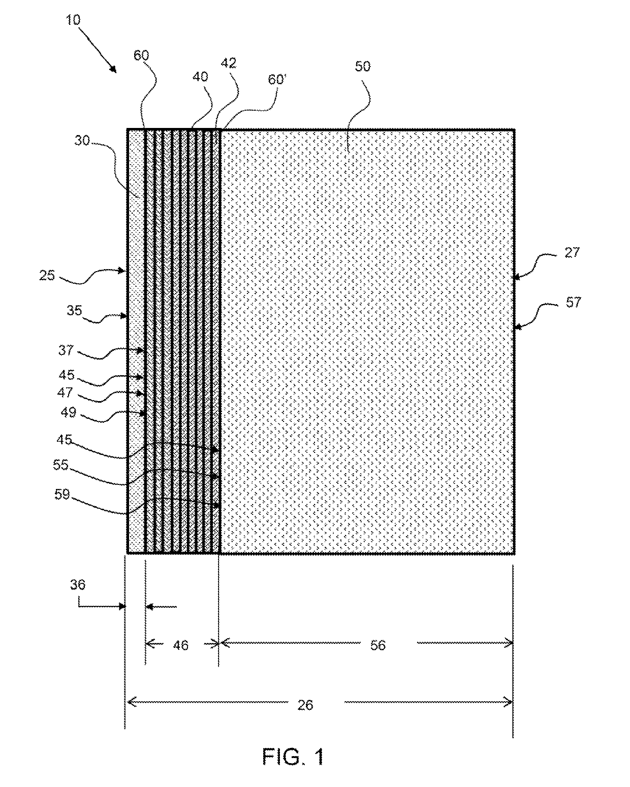
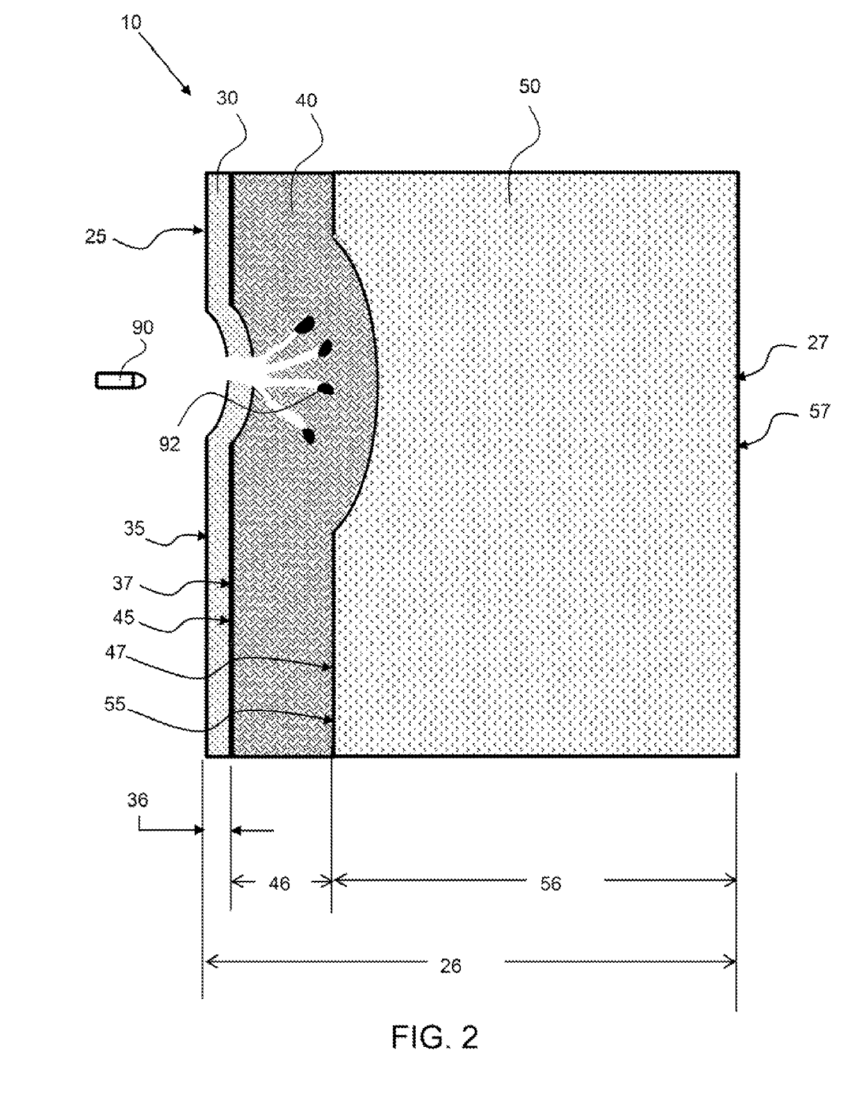
[0004]The invention is directed to a radome that provides ballistic protection and has low insertion loss in three bands. This is known as a tri-band radome. In an exemplary embodiment, a tri-band radome cover comprises an outside strike plate, a capture layer, and an inner tuning layer. The outside strike plate faces the ballistic threat and is configured to fracture, turn, blunt, or otherwise perturb, the projectile so that it can then be more easily captured by the capture layer. The strike plate layer also adds hermeticity to the radome as well as a tough outer surface that creates a barrier to abrasion and non-ballistic impacts. The capture layer is configured to stop the fragments of the bullet. The tuning layer is configured to reduce signal transmission loss by tuning-out reflective losses. The tuning layer also enhances the ballistic performance of the armor by reducing back-face deformation in addition to adding strength to the overall radome. The three layers of the composite may be adhered together with an adhesive and formed into a dome shape. In an exemplary embodiment, the three layers of the radome composite have diminishing dielectric constants from the outside layer to the inside layer, thereby minimizing overall reflective losses. An exemplary radome, as described herein, has an insertion loss within three bands over a frequency range of about 8 GHz to about 32 GHz of no more than 1 dB at a zero degree incident angle.

Problems solved by technology

Ballistic covers utilizing a capture layer only, such as those currently available, may be susceptible to water permeation through the fibrous layers of material.

Method used


Image

  • Low loss tri-band protective armor radome
  • Low loss tri-band protective armor radome
  • Low loss tri-band protective armor radome

Examples


Embodiment Construction

[0031]Corresponding reference characters indicate corresponding parts throughout the several views of the figures. The figures represent an illustration of some of the embodiments of the present invention and are not to be construed as limiting the scope of the invention in any manner. Further, the figures are not necessarily to scale, some features may be exaggerated to show details of particular components. Therefore, specific structural and functional details disclosed herein are not to be interpreted as limiting, but merely as a representative basis for teaching one skilled in the art to variously employ the present invention.

[0032]As used herein, the terms “comprises,”“comprising,”“includes.”“including.”“has,”“having” or any other variation thereof, are intended to cover a non-exclusive inclusion. For example, a process, method, article, or apparatus that comprises a list of elements is not necessarily limited to only those elements but may include other elements not expressly ...


PUM


Abstract

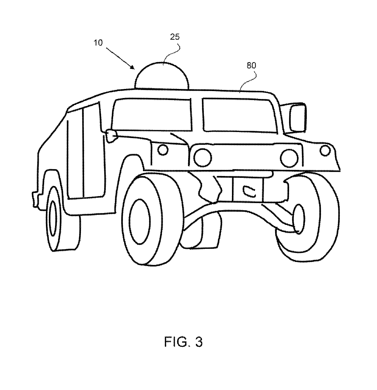
A tri-band multiwell radome includes a dense polymeric strike plate that is configured on the outside of the radome, a capture layer and a tuning layer. The polymeric strike plate is a tough polymer, such as a polycarbonate and breaks a bullet into fragments that are more easily captured by the capture layer. The capture layer includes a number of fabric sheets of highly oriented fibers, such as polyethylene fibers, and a binder. The tuning layer may be a low density foam that is configured inside of the capture layer and provided to reduce reflective losses and improve ballistic performance. A tri-band radome cover may have a dB loss over a wavelength of 8 to 40 kHz of no more than 1 dB. A tri-band radome cover may be formed in a dome shape.

Description

CROSS REFERENCE TO RELATED APPLICATION[0001]This application is a national stage entry application of international application no. PCT / US2017 / 039347 which claims the benefit of U.S. provisional patent application No. 62 / 355,301, filed on Jun. 27, 2016 and entitled Low Loss Tri-Band Armor Protective Radome; the entirety of which is incorporated by reference herein.BACKGROUND OF THE INVENTIONField of the Invention[0002]The present invention is directed to radomes that provide ballistic protection and have low insertion loss in multi-bands.Background[0003]A radome is a structural protective cover for an antenna, and in this case a multiband microwave antenna system. A radome traditionally provides protection from rain, dust, sand and is constructed of a material or materials whose dielectric properties and architecture (tuned layers of multiple materials) allow a high transmission efficiency of the microwave signals. Radomes are used to protect a wide variety of antennas from Doppler ...

Claims


Application Information

Patent Timeline
Patent Type & Authority Patents(United States)
IPC IPC(8): H01Q1/32H01Q1/42
CPCH01Q1/42H01Q1/32H01Q1/422H01Q1/3275H01Q1/3233
Inventor HAWTHORNE, MARK
Owner ATC MATERIALS INC
Why Eureka
Eureka Blog
Learn More