Display Device

a display device and display screen technology, applied in the field of display devices, can solve the problems of reducing affecting the image quality, so as to reduce the brightness of a single color, reduce the power, and improve the image quality.

Active Publication Date: 2009-08-20
PANASONIC LIQUID CRYSTAL DISPLAY CO LTD +1
View PDF4 Cites 78 Cited by
  • Summary
  • Abstract
  • Description
  • Claims
  • Application Information

AI Technical Summary

Benefits of technology

[0016]According to the present invention, deterioration in the image quality (darkness) due to the lowering in the brightness of a single color as a result of the conversion from RGB pixels to RGBW pixels can be avoided and a reduction in the power can be achieved.

Problems solved by technology

The demand for middle- and small-sized displays having ultrahigh resolution, such as UMPC's, has tended to increase in recent years, and a reduction in the power in the system has become a significant issue.
As a result, the brightness of a single color relative to white is low in the case where white and a single color are displayed, and thus a single color provides a dark image, and this is a factor in the deterioration of the image quality.

Method used


Image

  • Display Device
  • Display Device
  • Display Device

Examples


first embodiment

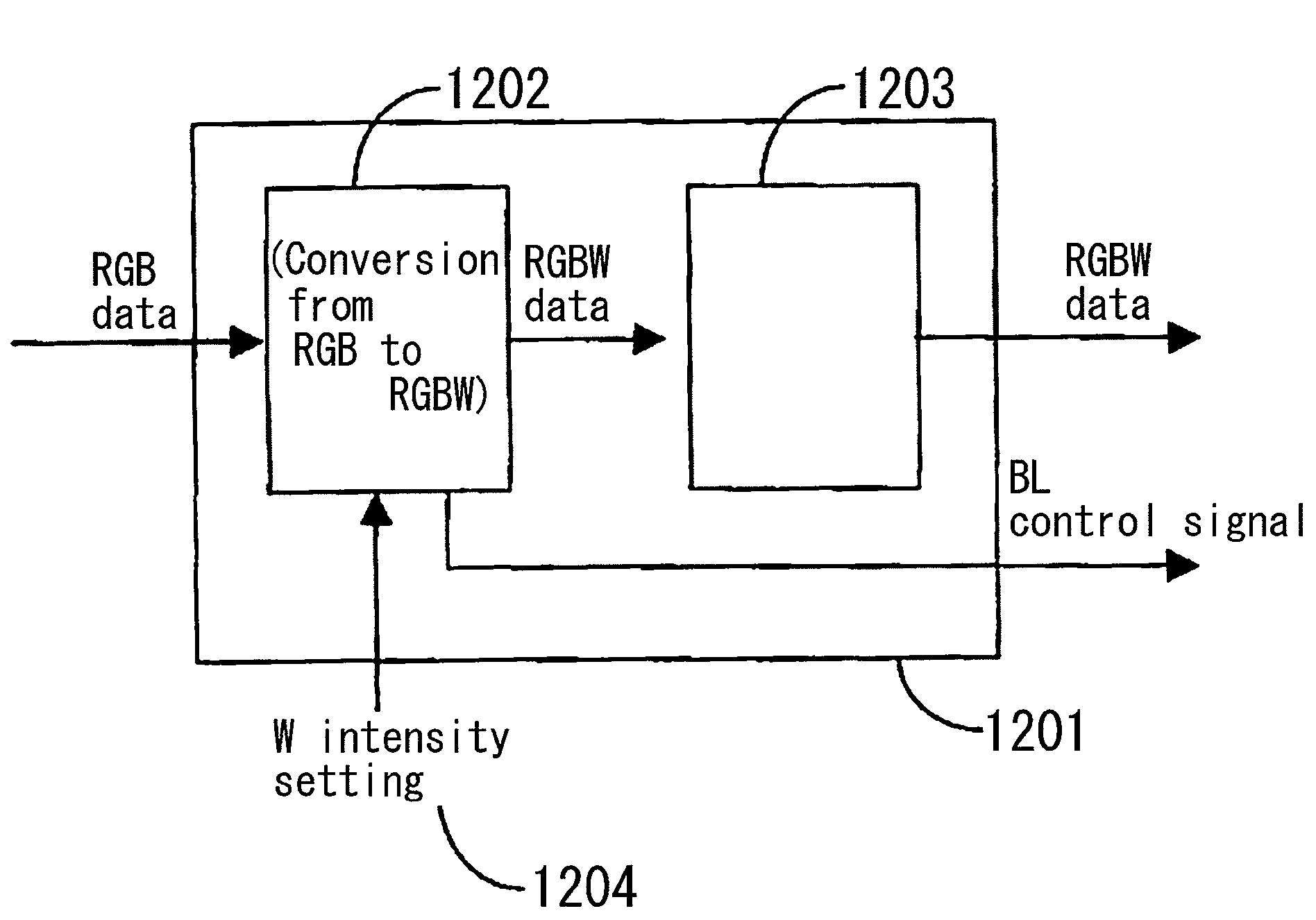
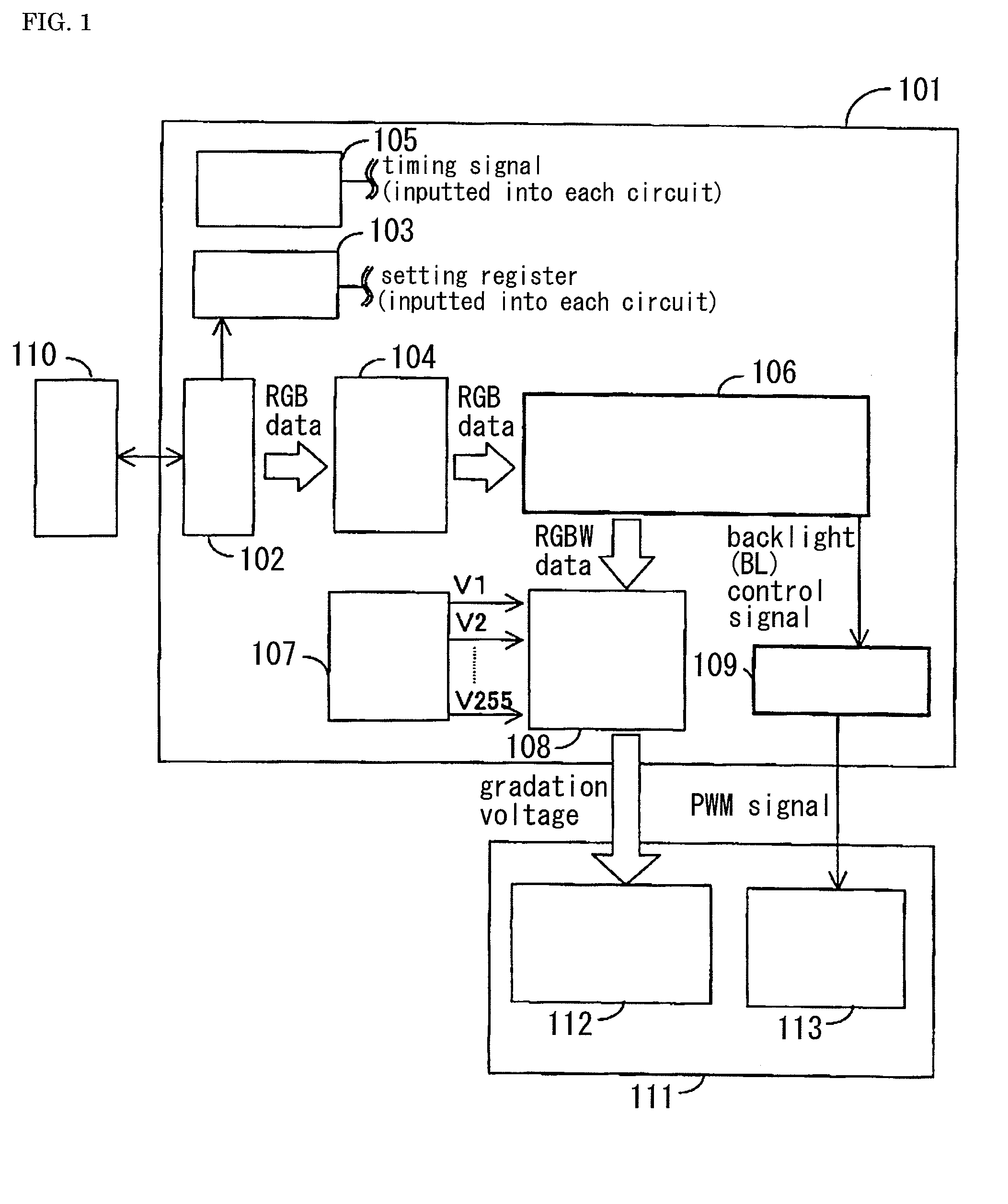
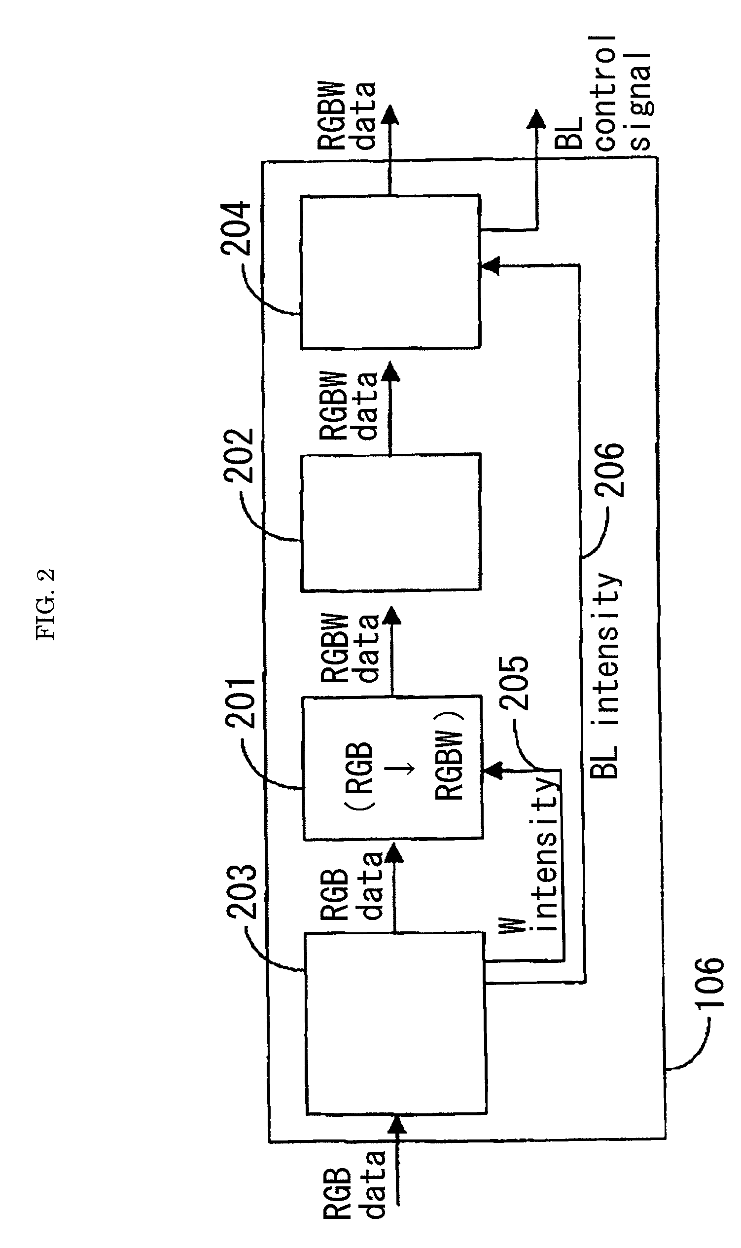
[0037]The first embodiment of the present invention is described in reference to FIGS. 1 to 5. The first embodiment is characterized by setting the W (white) intensity and BL (backlight) brightness ratio in accordance with the ratio of the saturation pixels and the ratio of the W pixels in the image data (for example, the ratio of the numbers within the image in one frame). FIG. 1 is a diagram showing the configuration of the data driver in the liquid crystal display device according to the first embodiment of the present invention. FIG. 2 is a diagram showing the configuration of the processing portion for conversion from RGB to RGBW in FIG. 1. FIG. 3 is a graph for the explanation of a method for calculating the W intensity in the W intensity calculating circuit in FIG. 2. FIG. 4 is a diagram showing the configuration of the W intensity calculating circuit in FIG. 2. FIG. 5 is a diagram showing the detailed configuration of the low power backlight control circuit in FIG. 2. Satura...

second embodiment

[0047]Next, the second embodiment of the present invention is described in reference to FIGS. 1, 2 and 6 to 8. The second embodiment is characterized in that the W intensity and the BL intensity are set in the same manner as in the first embodiment, and in addition the relational equation between the saturation ratio and the W intensity in the image data for calculating the W intensity is independent from among computer graphic images, user interface images (CG / UI images) and natural images / moving images, and thus the relational expression between the saturation ratio and the W intensity in the above described image data is selected through the setting of the register.

[0048]FIGS. 1 and 2 show the second embodiment in the same manner as in the first embodiment. FIG. 6 is a graph for the explanation of the method for calculating the W intensity in the W intensity calculating portion in FIG. 2 according to the second embodiment. FIG. 6(B) is different from FIG. 3(B) used for the explan...

third embodiment

[0053]Next, the third embodiment of the present invention is described in reference to FIGS. 1, 2, 6 and 9 to 11. The third embodiment has a relational expression between the saturation ratio and the W intensity independent in the CG / UI images and in the natural images / moving images, respectively, in the same manner as in the second embodiment, and in addition the above described two relational expressions are characterized by being determined when the image data automatically detects whether the image is characterized as a CG / UI image or as a natural image / moving image. FIGS. 1 and 2 show the third embodiment in the same manner as the first embodiment.

[0054]FIG. 9 is a graph for the explanation of a method for determining whether the image is characteristic as a CG / UI image or the image is characteristic as a natural image / moving image from the relational expression between the saturation ratio and the W intensity in FIG. 6 as described in the second embodiment. FIG. 9(A) shows an ...


PUM


Abstract

The deterioration (darkness) of image quality due to a reduction in the brightness of a single color as a result of the conversion from RGB pixels to RGBW pixels is prevented and a reduction in the power is achieved. A processing portion for conversion from RGB to RGBW 106 is formed of a W generating circuit 201, which is the same as in the prior art, a sub-pixel rendering circuit 202, a W intensity calculating portion 203 which transmits a W intensity setting value 205 to a W generating circuit 201, and a low power backlight control circuit 204 which expands data on the basis of the RGBW pixels generated by the sub-pixel rendering portion 202 and lowers the backlight in accordance with the amount by which the data is expanded. The inputted RGB data is used as the RGBW data with the W intensity calculated by the W intensity calculating portion 203. A backlight control signal is generated in accordance with the amount of data expansion in the sub-pixel rendering portion 202.

Description

BACKGROUND OF THE INVENTION[0001]The present invention relates to a display device formed of an RGBW display panel module where an increase in brightness and a reduction in power consumption can be achieved, and which is improved upon with regards to a darkness in single colors, and in particular to a liquid crystal display device having a backlight.[0002]The demand for middle- and small-sized displays having ultrahigh resolution, such as UMPC's, has tended to increase in recent years, and a reduction in the power in the system has become a significant issue. In this situation, RGBW pixel panels where white (W) sub-pixels (hereinafter referred to as W pixels) are added to conventional sub-pixels of red (R), green (G) and blue (B) (hereinafter referred to as RGB pixels) make it possible for the brightness to be increased, and therefore makes it possible to achieve a reduction in the power by reducing the scale of backlight, and thus it is considered that demand will increase in the f...

Claims


Application Information

Patent Timeline
Patent Type & Authority Applications(United States)
IPC IPC(8): G09G5/02
CPCG09G3/3406G09G3/3607G09G2360/16G09G2320/0276G09G2320/0646G09G2320/0261
Inventor TAKADA, NAOKIKUDO, YASUYUKIKUROKAWA, YOSHIKIMAMBA, NORIOKOMURA, SHINICHI
Owner PANASONIC LIQUID CRYSTAL DISPLAY CO LTD
Why Eureka
Try Eureka