Spent fuel storage rack

a technology of spent fuel and storage rack, which is applied in the direction of nuclear engineering problems, greenhouse gas reduction, nuclear elements, etc., can solve the problems of limited amount of boron to be added, inability to absorb neutrons, so as to achieve the effect of reducing the amount of welding in the lattice body and sufficient absorban

Active Publication Date: 2009-08-20
KK TOSHIBA
View PDF4 Cites 10 Cited by
  • Summary
  • Abstract
  • Description
  • Claims
  • Application Information

AI Technical Summary

Benefits of technology

[0016]According to the present invention, the main lattice, which is located on a position corresponding to the fuel assemblies and has a height equivalent to an active length of the fuel assembly, is fitted in the upper lattice and the lower lattice and secured thereto. Thus, when the main lattice is assembled and secured, it is not necessary to perform a welding operation to the main lattice. Thus, as a material for the main lattice, it is possible to employ a boron-added stainless steel to which a sufficient amount of boron is added to absorb neutrons. Accordingly, the main lattice can have a sufficient ability to absorb neutrons.
[0017]In addition, according to the present invention, since it is not necessary to perform a welding operation to the main lattice for securing the main lattice, a welding amount in the lattice body can be significantly reduced as a whole. Further, the present invention eliminates the use of a special jig for the welding operation performed in the narrow lattice-like cells, which is economically advantageous.

Problems solved by technology

However, the boron-added stainless steel has a following disadvantageous feature.
Namely, as an amount of added boron increases, a welding operation is more likely to impair a material strength of the boron-added stainless steel.
Thus, when lattice plate members using the boron-added stainless steel are integrated by welding to form a lattice plate, an amount of boron to be added is limited, which limits an ability to absorb neutrons.
Further, when lattice plate members are integrated by welding to form a lattice plate, the welding operation is complicated, because lattice-like cells are adjacent to each other.
Furthermore, since the welding operation has to be performed in the narrow lattice-like cells, it is necessary to use a special jig, which is economically disadvantageous.

Method used


Image

  • Spent fuel storage rack
  • Spent fuel storage rack
  • Spent fuel storage rack

Examples


first embodiment

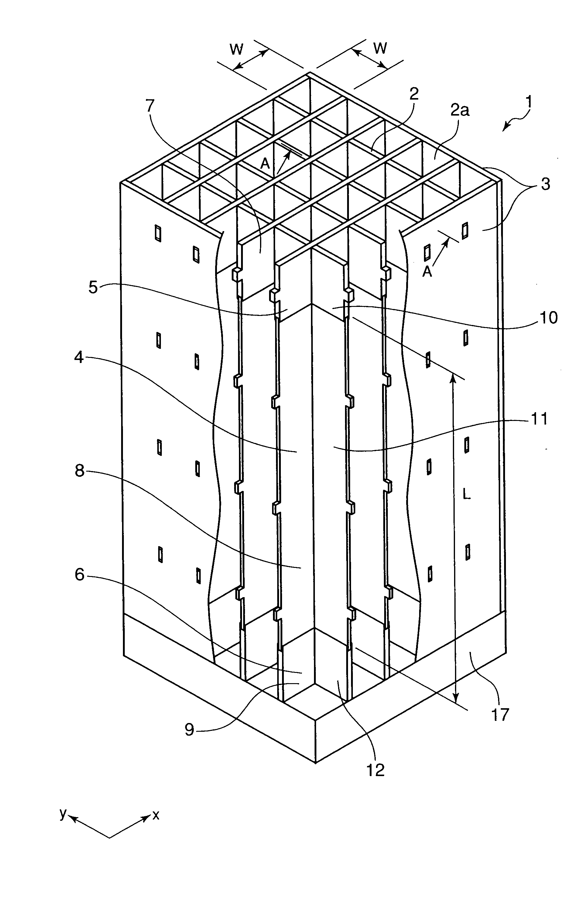
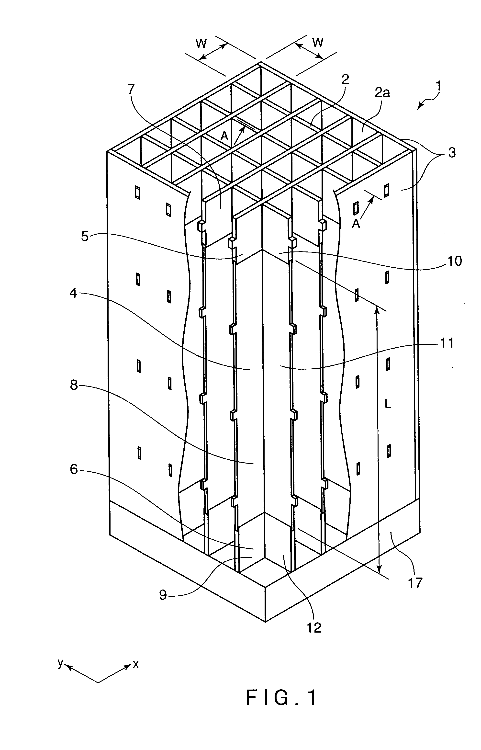
[0025]Embodiments of the present invention will be described with reference to the drawings. FIGS. 1 to 6 are views showing a first embodiment of a spent fuel storage rack according to the present invention. FIG. 1 is a perspective view showing an overall structure of the spent fuel storage rack. FIG. 2 is a perspective view showing structures of respective lattice parts. FIG. 3 is a cross-sectional view taken along the line A-A in FIG. 1. FIG. 4 is a cross-sectional view taken along the line B-B in FIG. 3. FIG. 5 is a cross-sectional view taken along the line C-C in FIG. 3. FIG. 6 is a cross-sectional view taken along the line D-D in FIG. 3.

[0026]The overall structure of the spent fuel storage rack 1 in the first embodiment of the present invention is described at first, with reference to FIG. 1. The spent fuel storage rack 1 according to the present invention is installed in a fuel storage pool of a nuclear facility, and has a rectangular parallelepiped shape forming a plurality o...

second embodiment

[0059]Next, a second embodiment of the spent fuel storage rack according to the present invention will be described with reference to FIG. 7. FIG. 7 is a perspective view showing respective lattice parts.

[0060]In the second embodiment shown in FIG. 7, a flat lattice plate for upper lattice 7 constituting an upper lattice 5 is divided into lattice plates 18 at intersection points where the flat lattice plate for upper lattice 7 crosses the strip-like lattice plates for upper lattice 10. Other structures are substantially the same as those of the first embodiment shown in FIGS. 1 to 6.

[0061]In the embodiment shown in FIG. 7, the same parts as those of the first embodiment shown in FIGS. 1 to 6 are indicated by the same reference numbers, and detailed description thereof is omitted. A groove 15 in which an upper end surface 4a of a main lattice 4 is fitted is formed in lower end surfaces of the divided lattice plates 18 of the flat lattice plate for upper lattice 7. The groove 15 in wh...

third embodiment

[0064]Next, a third embodiment of the spent fuel storage rack according to the present invention is described with reference to FIGS. 1 to 6.

[0065]It can be expected that a higher ability to absorb neutrons is required for the spent fuel storage rack 1 because of an increased burn-up of fuels in the future.

[0066]In the third embodiment, an outer frame 3, an upper lattice 5, and a lower lattice 6 are made of a boron-added stainless steel having a smaller amount of added boron than that of a main lattice 4, or an enriched boron-added stainless steel. Other structures of the third embodiment are substantially the same as those of the first embodiment shown in FIGS. 1 to 6.

[0067]In this embodiment, the outer frame 3, the upper lattice 5, and the lower lattice 6 may be made of a boron-added stainless steel having a smaller amount of added boron than that of the main lattice 4, or an enriched boron-added stainless steel. In this case, even when the outer frame 3, the upper lattice 5, and ...


PUM


Abstract

A spent fuel storage rack 1 according to the present invention is installed in a fuel storage pool of a nuclear facility, and has a rectangular parallelepiped shape forming a plurality of lattice-like cells 2a that are configured to separately accommodate a plurality of fuel assemblies in a matrix of rows and columns. As shown in FIG. 1, the spent fuel storage rack 1 includes: a base 17 configured to support lower parts of fuel assemblies, the base 17 forming a bottom surface of the spent fuel storage rack 1; an outer frame 3 located above the base 17, the outer frame 3 forming an outermost periphery of the spent fuel storage rack 1; and a lattice body 2 disposed inside the outer frame 3, the lattice body 2 forming the lattice-like cells 2a. The lattice body 2 includes: a main lattice 4 having a height equivalent to an active length of the fuel assembly; an upper lattice 5 disposed above the main lattice 4 so as to be fitted to an upper end of the main lattice 4; and a lower lattice 6 disposed between the base 17 and the main lattice 4 so as to be fitted to a lower end of the main lattice 4. Thus, the main lattice 4 can be formed without welding, whereby the main lattice 4 can be made of a boron-added stainless steel to which a sufficient amount of boron is added to absorb neutrons.

Description

FIELD OF THE INVENTION[0001]The present invention relates to a spent fuel storage rack installed in a fuel storage pool of a nuclear facility, the spent fuel storage rack having a rectangular parallelepiped shape forming lattice-like cells that are configured to separately accommodate a plurality of fuel assemblies in a matrix of rows and columns. In particular, the present invention pertains to a spent fuel storage rack to which a neutron absorption function can be imparted.BACKGROUND ART[0002]In an atomic power plant, spent fuels, which are taken out from a reactor core after an atomic power reactor has been operated for a certain period of time, are conventionally accommodated and stored in a spent fuel storage rack installed in a fuel storage pool, until a reprocessing is performed. In the spent fuel storage rack, the spent fuels are cooled for removing a decay heat thereof. In recent years, it has been required to increase a storage capacity of spent fuels by effectively utiliz...

Claims


Application Information

Patent Timeline
Patent Type & Authority Applications(United States)
IPC IPC(8): G21C19/07
CPCG21C19/07G21C19/40G21Y2004/30G21Y2002/201G21Y2002/302G21Y2002/10Y02E30/30
Inventor MAEDA, MANABU
Owner KK TOSHIBA
Why Eureka
Try Eureka