Head-related transfer function measurement method, head-related transfer function convolution method, and head-related transfer function convolution device

Active Publication Date: 2009-08-20
SONY CORP
View PDF12 Cites 51 Cited by
  • Summary
  • Abstract
  • Description
  • Claims
  • Application Information

AI Technical Summary

Benefits of technology

[0032]Also, in the normalizing, an amount of data equivalent to the time from the sound waves emitted at the perceived sound source position to directly reach the acousto-electric conversion unit may be eliminated from the head-related transfer function and the natural-state transfer property obtained in the first measuring and the second measuring, with the normalization processing being performed, and in t

Problems solved by technology

However, the measured HRTFs still include the properties of the microphones serving as an audio-electric conversion unit used for measurement, speakers serving as the sound source at the time of measurement, the room where the measurement was performed, and so on, so there is a problem that the properties and sound quality of reproduced audio is affected by the properties of the microphones used for measurement, the speakers serving as the sound source at the time of measurement, and the room or place where the measurement was performed.
However, even such expensive microphones and speakers do not yield ideally flat frequency properties, so there have been cases wherein the effects of the properties of such microphones and speakers could not be completely

Method used


Image

  • Head-related transfer function measurement method, head-related transfer function convolution method, and head-related transfer function convolution device
  • Head-related transfer function measurement method, head-related transfer function convolution method, and head-related transfer function convolution device
  • Head-related transfer function measurement method, head-related transfer function convolution method, and head-related transfer function convolution device

Examples


Embodiment Construction

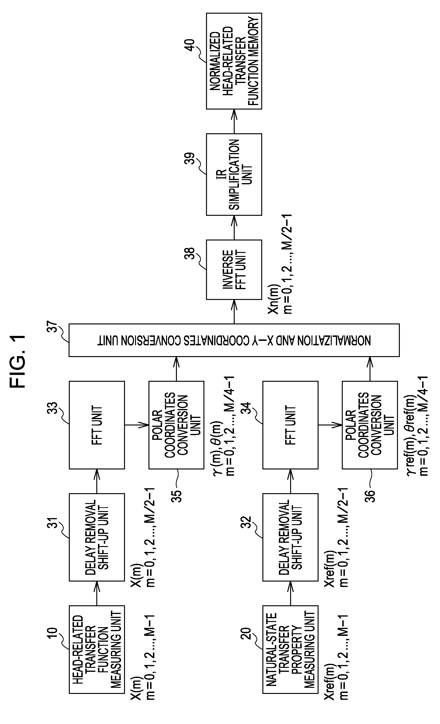
[0045]Description of HRTF Measurement Method First, an HRTF (head-related transfer function) measurement method according to an embodiment of the present invention will be described with reference to the drawings. FIG. 1 is a block diagram of a configuration example of a system for executing processing procedures for obtaining data for a normalization HRTF used with the HRTF measurement method according to an embodiment of the present invention. With this example, an HRTF measurement unit 10 performs measurement of HRTFs in an anechoic chamber, in order to measure head-related transfer properties of direct waves alone.

[0046]With the HRTF measurement unit 10, in the anechoic chamber, a dummy head or an actual human serving as the listener is situated at the position of the listener, and microphones serving as an acousto-electric conversion unit for collecting sound waves for measurement are situated at positions (measurement point positions) nearby both ears of the dummy head or huma...


PUM


Abstract

A head-related transfer function measurement method includes the steps of: first measuring, including placing an acousto-electric conversion unit nearby both ears of a listener where placement of an electro-acoustic conversion unit is assumed, picking up sound waves emitted at a perceived sound source position with the acousto-electric conversion unit in a state with a dummy head or a human at the listener position, and measuring a head-related transfer function from only the sound waves directly reaching the acousto-electric conversion unit; second measuring, including picking up sound waves emitted at a perceived sound source position with the acousto-electric conversion unit, with no dummy head or human at the listener position, and measuring a natural-state transfer property from only the sound waves directly reaching the acousto-electric conversion unit; normalizing the head-related transfer function with the natural-state transfer property to obtain a normalized head-related transfer function; which is stored in a storage unit.

Description

CROSS REFERENCES TO RELATED APPLICATIONS[0001]The present invention contains subject matter related to Japanese Patent Application JP 2008-034236 filed in the Japanese Patent Office on Feb. 15, 2008, the entire contents of which are incorporated herein by reference.BACKGROUND OF THE INVENTION[0002]1. Field of the Invention[0003]The present invention relates to a method for measuring a head-related transfer function (hereafter abbreviated to “HRTF”) for enabling a listener to hear a sound source situated in front or the like of the listener, during acoustic reproduction with an electric-acoustic unit such as an acoustic reproduction driver of headphones for example, which is disposed near the ears of the listener.[0004]2. Description of the Related Art[0005]In a case of the listener wearing the headphones on the head for example, and listening to acoustically reproduced signals with both ears, if the audio signals reproduced at the headphones are commonly-employed audio signals suppl...

Claims


Application Information

Patent Timeline
IPC IPC(8): H04R5/00
CPCH04S2420/01H04S1/005H04R5/033H04S3/004
Inventor FUKUI, TAKAONISHIO, AYATAKA
Owner SONY CORP
Why Eureka
Try Eureka