Waveguide type optical isolator and magnet holder used in waveguide type optical isolator

a technology of optical isolators and magnet holders, which is applied in the direction of optical waveguide light guides, instruments, optics, etc., can solve the problems of extremely low population accuracy of magnets, deformation of oscillation characteristics of semiconductor lasers, and unintentional incidence of deformation of operating characteristics of elements, so as to prevent the magnets from separating, fix the magnet over a long period of time, and high accuracy

Inactive Publication Date: 2009-08-20
MITSUMI ELECTRIC CO LTD
View PDF24 Cites 5 Cited by
  • Summary
  • Abstract
  • Description
  • Claims
  • Application Information

AI Technical Summary

Benefits of technology

[0023]According to the waveguide type optical isolator of the present invention, the small permanent magnets constituting the magnetic field applying means are used by housing and fixing in the magnet holder, and thereby it is possible to populate the magnets at appropriate positions on the magnetic garnet with the high accuracy.
[0024]Further, since the mounted distance between the two magnets is fixed by the second protruded portion of the magnet holder, it is possible to prevent the magnets from separating from the magnetic garnet by the repulsive stress or the like between the magnets. Therefore, it is possible to fix the magnet over a long period of time.
[0025]Furthermore, since the side portions of the first protruded portion and the third protruded portion of the magnet holder extend up to the upper surface of the package substrate, in addition, the substrate, the waveguiding layer (the waveguides), the magnetic garnet, and the magnetic field applying means are be housed and fixed within the magnet holder, and thereby it is possible to fix the magnets over a long period of time, in addition, to guarantee the long-term reliability of the entire waveguide type optical isolator.

Problems solved by technology

Unless the optical isolator is placed at the emitting end of the semiconductor laser, a reflected return light will be incident on the semiconductor laser, and thereby a degradation of oscillation characteristics of the semiconductor laser is caused.
In optical active elements such as not only the aforementioned semiconductor laser but also an optical amplifier or the like, operating characteristics of the element are degraded by unintentional incidence of light from an opposite direction.
Therefore, it is very difficult to populate the permanent magnet 105 at an appropriate position on the magnetic garnet 104, and thereby population accuracy of the magnet is extremely low.

Method used


Image

  • Waveguide type optical isolator and magnet holder used in waveguide type optical isolator
  • Waveguide type optical isolator and magnet holder used in waveguide type optical isolator
  • Waveguide type optical isolator and magnet holder used in waveguide type optical isolator

Examples


Embodiment Construction

[0035]Hereinafter, a waveguide type optical isolator according to the present invention and a magnet holder used in the waveguide type optical isolator according to the present invention will be described with reference to the drawings.

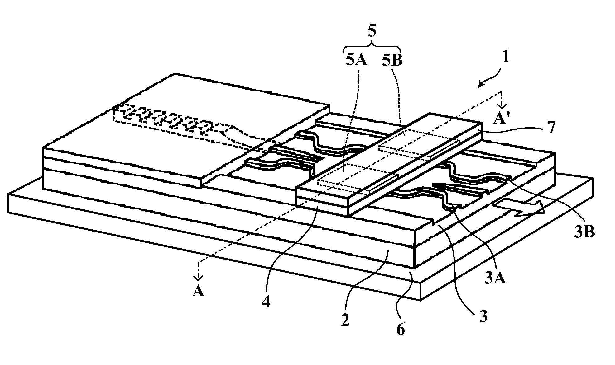
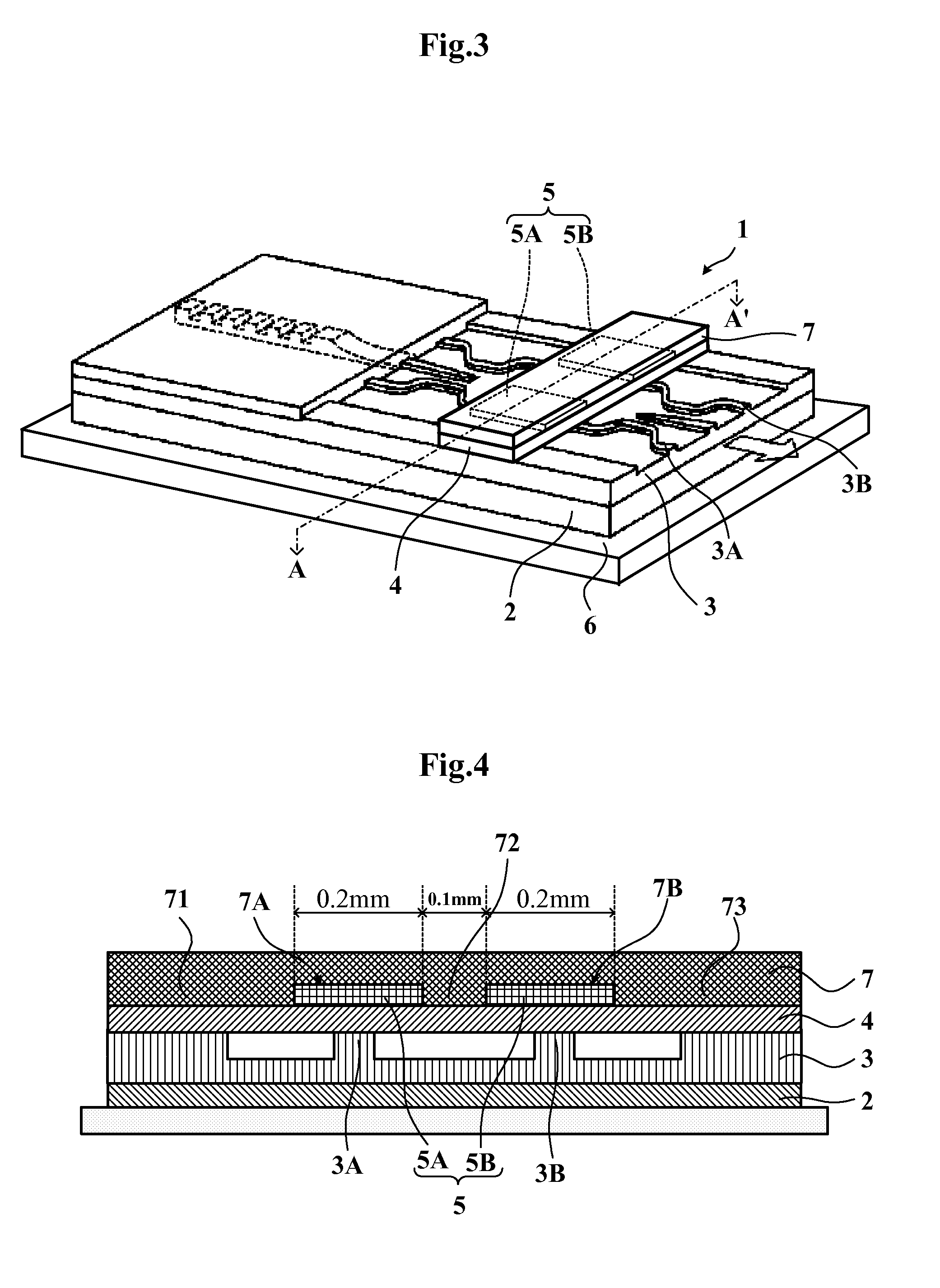
[0036]FIG. 3 is a perspective view of a waveguide type optical isolator according to the present invention, and FIG. 4 is a cross-sectional view of A-A′ in FIG. 3.

[0037]As shown in the figures, the waveguide type optical isolator 1 comprises a substrate 2, a waveguiding layer 3, a magnetic garnet 4, and magnetic field applying means 5, and they are set on a package substrate (support substrate) 6. And two waveguides 3A and 3B are formed in the waveguiding layer 3. Namely, the waveguide type optical isolator 1 is constituted by providing the waveguiding layer 3 which is formed on the substrate 2 which is a compound semiconductor substrate (an InP substrate in the present embodiment) using a semiconductor material so as to be lattice-matched to the subs...


PUM


Abstract

A waveguide type optical isolator comprises a substrate, a waveguiding layer provided with waveguides, a magnetic garnet, magnetic field applying means, and a package substrate, wherein a first magnet and a second magnet is provided as the magnetic field applying means, and the first magnet and the second magnet are housed and fixed within a magnet holder.

Description

TECHNICAL FIELD[0001]The present invention relates to a waveguide type optical isolator and a magnet holder used in such an isolator, and more particularly, relates to a waveguide type optical isolator and a magnet holder used in the waveguide type optical isolator which can improve the population accuracy of the magnets being used as magnetic field applying means and also fix the magnets over a long period of time.BACKGROUND TECHNOLOGY[0002]An optical isolator is an element which allows light to transmit only in one direction but prevents the light from propagating in a opposite direction thereto. For example, by arranging the optical isolator at an emitting end of a semiconductor laser, the light emitted from the semiconductor laser transmits through the optical isolator, and it is possible to be used this light as a light source for optical fiber communications. Conversely, the light which is going to be incident on the semiconductor laser through the optical isolator prevents by...

Claims


Application Information

Patent Timeline
Patent Type & Authority Applications(United States)
IPC IPC(8): G02B6/12
CPCG02F1/0955G02F2201/063G02F2001/212G02F1/212G02B27/28G02F1/095
Inventor NAKAJIMA, IKUOHAYAKAWA, ETSUJIMIZUMOTO, TETSUYA
Owner MITSUMI ELECTRIC CO LTD
Why Eureka
Try Eureka