
Cooling system for fuel cell stack shutdown

a fuel cell and cooling system technology, applied in the direction of transportation fuel cell technology, hydrogen technology, electric generators, etc., can solve the problems of inability to meet the requirements of fuel cell operation, and corrosion of catalysts and catalyst assemblies, so as to reduce the effective cell life, eliminate voltage persistence, and minimize the effect of voltage persisten

Active Publication Date: 2009-08-20
HONDA MOTOR CO LTD
View PDF9 Cites 17 Cited by
  • Summary
  • Abstract
  • Description
  • Claims
  • Application Information

AI Technical Summary

Benefits of technology

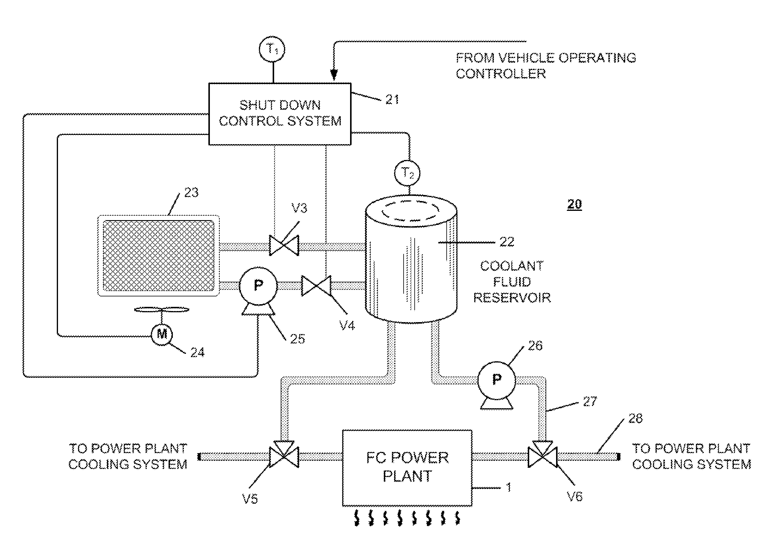
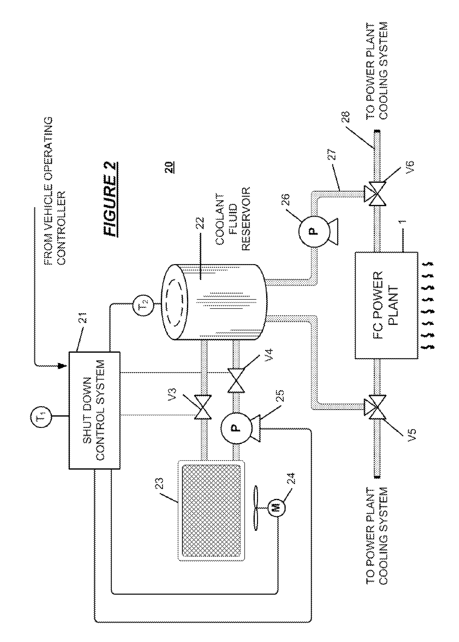
The present invention provides a cooling system for the shut down operation of a vehicle fuel cell to minimize voltage persistence and the resulting damage to the cells. The cooling system eliminates voltage persistence by quickly cooling the fuel cell to ambient level using a secondary coolant reservoir containing liquid coolant at ambient temperature. This prevents the detrimental effects of catalytic activity caused by a temperature difference and ensures effective cell life.

Problems solved by technology

In fuel cells, when the electrical circuit leading to a powered device, such as an automobile drive system, is opened during shut down of the cell and the cell is relieved of an electrical load, the presence of air on the cathode, coupled with hydrogen fuel remaining on the anode, causes unacceptable anode and cathode potentials, resulting in corrosion in the catalyst and the catalyst assembly support and consequent degradation of the cell assembly and the cell performance.
In a motor vehicle, an on board supply of inert gas such as nitrogen for use in the shut down purge adds weight and cost and may interfere with vehicle shut-down and start-up procedures.
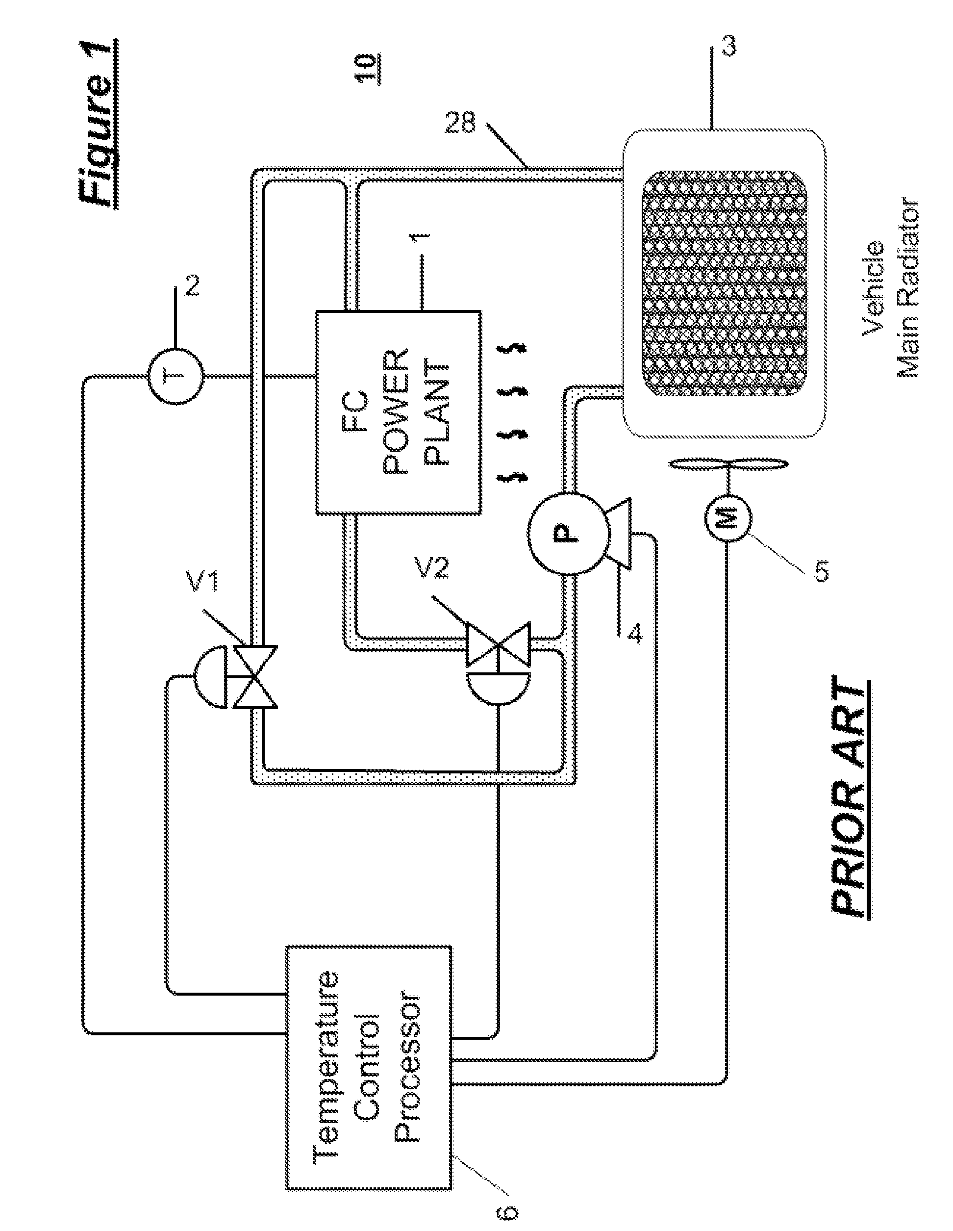
When the vehicle water pump is stopped, coolant remains in the fuel cell stack and cooling system, but, nevertheless, some hydrogen still remains at the anode side and produces a persistent voltage after a lapse of several hours.
The persistent voltage in an inoperative cell will cause membrane damage.
Generated heat in the fuel cell that causes hydrogen and air to react at the mixture front may cause some damage locally when this procedure is employed.

Method used


Image

  • Cooling system for fuel cell stack shutdown
  • Cooling system for fuel cell stack shutdown
  • Cooling system for fuel cell stack shutdown

Examples


Embodiment Construction

[0013]The invention provides a cooling system for vehicle fuel cell stacks that eliminates the hot condition in the fuel cell just after shut down and mitigates the catalyst active effect that causes degradation of the fuel cell assembly components. In the invention, the fuel cell cooling system is provided with a secondary cooling circuit with a reservoir which has a high heat dissipation wall. When the fuel cell powered vehicle is running and consuming fuel cell power, the coolant in the second reservoir is cooled to ambient temperature. After shut down of the generation of electricity by the fuel cell stack, a water pump moves the coolant from the supplemental reservoir into the fuel cell stack to replace the typically hot, conventional, fuel cell coolant quickly. Thus, the temperature of the fuel cell catalyst component is decreased to ambient temperature immediately; there is no heat or temperature difference between the stack and ambient temperature and residual voltage produc...


PUM

PropertyMeasurementUnit
open circuit voltageaaaaaaaaaa
temperatureaaaaaaaaaa
corrosionaaaaaaaaaa

Abstract

A cooling system for the shutdown process in a fuel cell powered vehicle system for eliminating the detrimental effects of voltage persistence in the fuel cell including a volume of fluid coolant at ambient temperature, a pump, a fluid circuit interconnecting the pump and the coolant reservoir with a section of a cooling system that circulates through the vehicle fuel cell stack, and a controllable valve system whereby, at the occurrence of vehicle shutdown, the ambient temperature fluid in the reservoir is directed to a section of a cooling system that circulates through the vehicle fuel cell stack.

Description

FIELD OF THE INVENTION[0001]The present invention relates to a cooling system for a fuel cell stack, operative at the time of shutdown, to reduce corrosion in the membrane and electrode assembly of the fuel cell caused by residual voltage generation effects.BACKGROUND OF THE INVENTION[0002]In fuel cells, when the electrical circuit leading to a powered device, such as an automobile drive system, is opened during shut down of the cell and the cell is relieved of an electrical load, the presence of air on the cathode, coupled with hydrogen fuel remaining on the anode, causes unacceptable anode and cathode potentials, resulting in corrosion in the catalyst and the catalyst assembly support and consequent degradation of the cell assembly and the cell performance. Conventionally, an inert gas is used to purge both the anode flow field and the cathode flow field immediately upon cell shut-down to dissipate electrical potential at the anode and cathode. In a motor vehicle, an on board supp...

Claims


Application Information

Patent Timeline
Patent Type & Authority Applications(United States)
IPC IPC(8): H01M8/04
CPCH01M8/04029H01M8/04067Y02T90/32Y02E60/50H01M2250/20H01M8/04223H01M8/04228Y02T90/40
Inventor MATSUO, SHIRO
Owner HONDA MOTOR CO LTD
Learn More