High-density ion transport measurement biochip devices and methods

a biochip and high-density ion technology, applied in the field of high-density ion transport measurement biochip devices and methods, can solve the problems of high operator skill and time, met with little success, and the inability to automate the patch clamp method, so as to facilitate the measurement of the ion channel of the cell, enhance the sealing properties, and enhance the sealing properties

Inactive Publication Date: 2009-08-20
AVIVA BIOSCI
View PDF100 Cites 12 Cited by
  • Summary
  • Abstract
  • Description
  • Claims
  • Application Information

AI Technical Summary

Benefits of technology

[0010]The present invention provides biochips for ion transport measurement, ion transport measuring devices that comprise biochips, and methods of using the devices and biochips that allow for the direct analysis of ion transport functions or properties. The present invention provides biochips, devices, apparatuses, and methods that allow for automated detection of ion transport functions or properties. The present invention also provides methods of making biochips and devices for ion transport measurement that reduce the cost and increase the efficiency of manufacture, as well as improve the performance of the biochips and devices. These biochips and devices are particularly appropriate for automating the detection of ion transport functions or properties, particularly for screening purposes.
[0020]A tenth aspect of the present invention is a method for storing the substrates, biochips, cartridges, apparatuses, and / or devices comprising ion transport measuring means with enhanced electrical seal properties.
[0021]An eleventh aspect of the present invention is a method for shipping the substrates, biochips, cartridges, apparatuses, and / or devices comprising ion transport measuring means with enhanced electrical seal properties.
[0029]A nineteenth aspect of the present invention is an ion channel chip or biochip utilizing a lipid layer or lipid bilayer for enhancing the sealing properties. The lipid bilayer is capable of interacting with the membrane of a cell having to facilitate measurement of a cell's ion channel.

Problems solved by technology

These and later methods relied upon interrogating one sample at a time using large laboratory apparatus that require a high degree of operator skill and time.
Attempts have been made to automate patch clamp methods, but these have met with little success.
Unfortunately, these methods do not measure ion transport directly but measure the change of indirect parameters as a result of ionic flux.

Method used


Image

  • High-density ion transport measurement biochip devices and methods
  • High-density ion transport measurement biochip devices and methods
  • High-density ion transport measurement biochip devices and methods

Examples


example 1

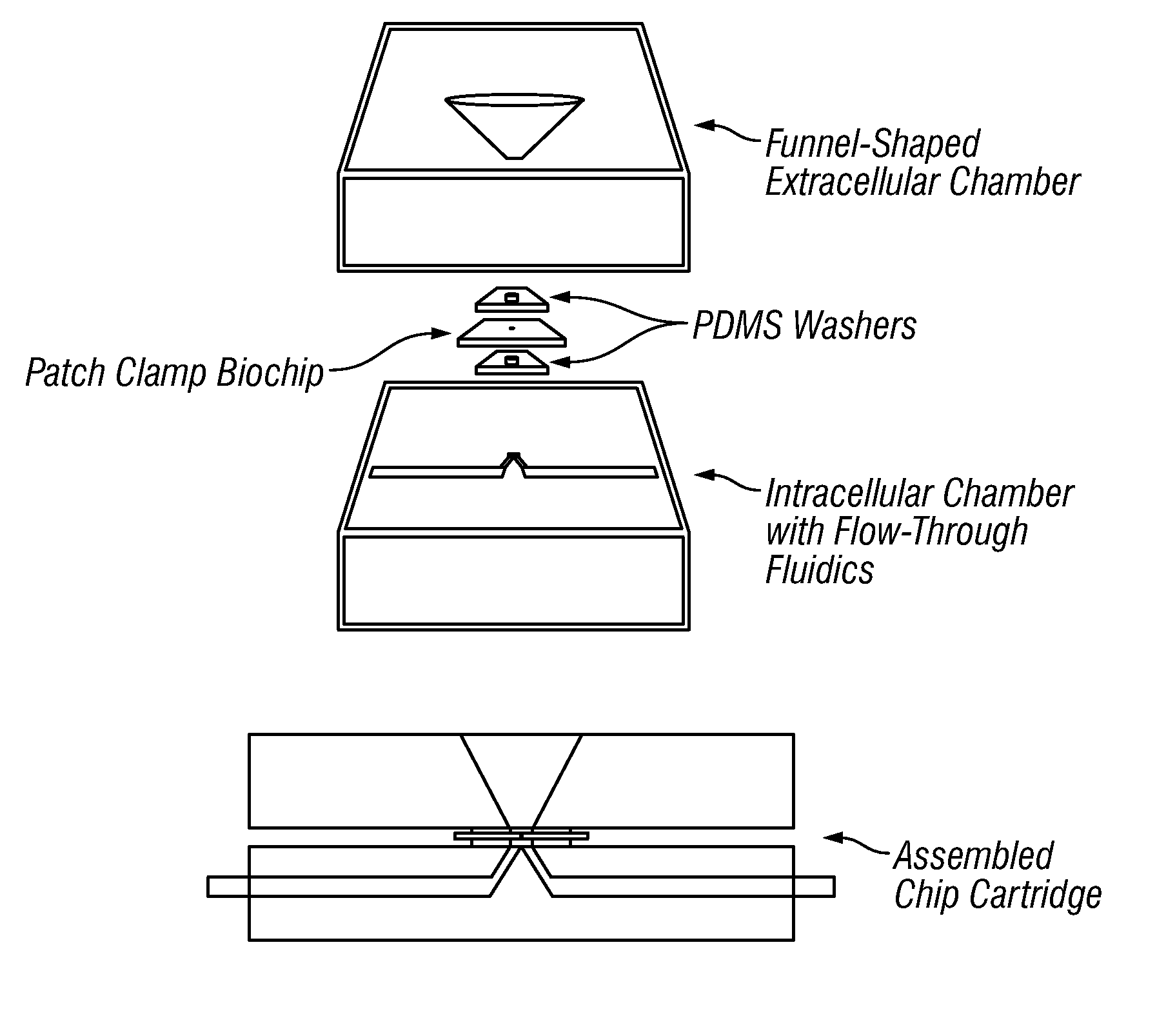
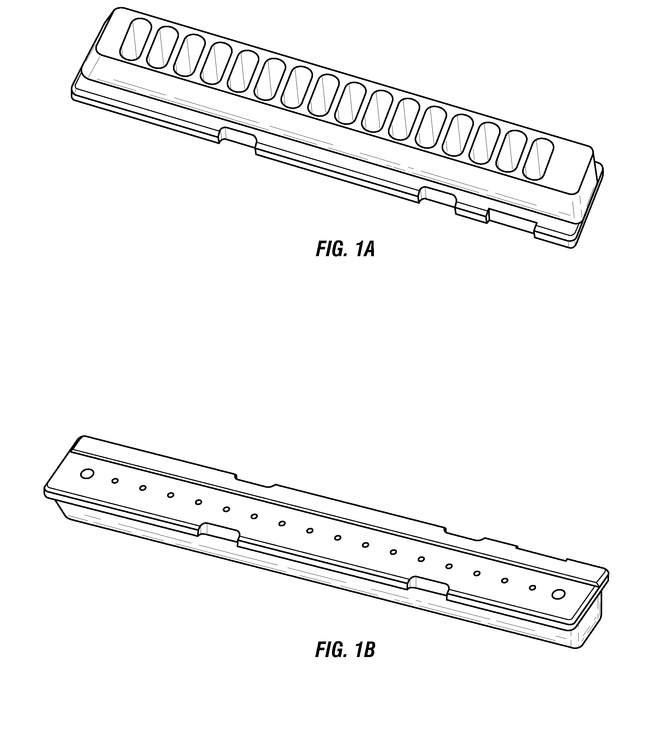
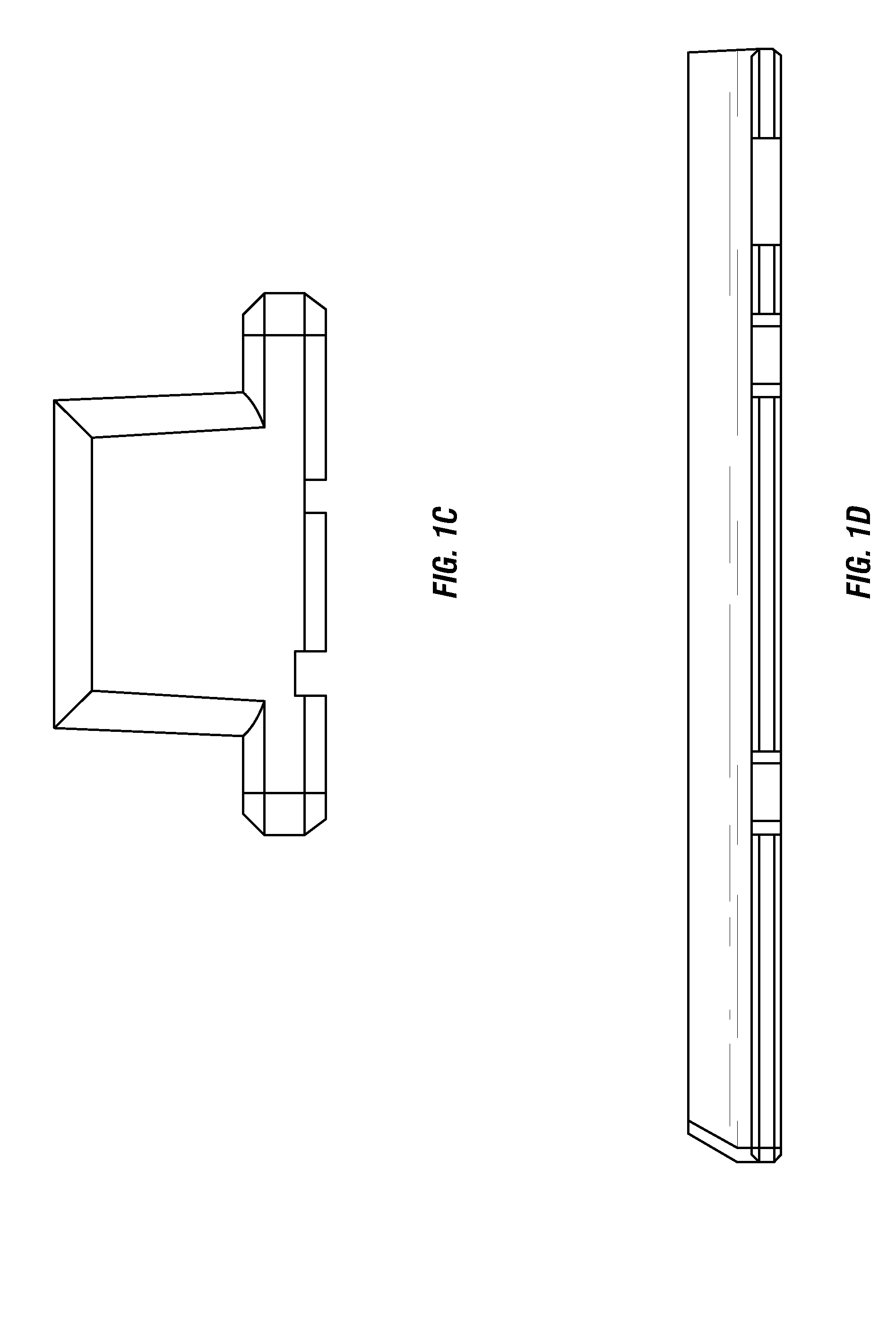
Device for Ion Transport Measurement Comprising Upper Chamber Piece and Biochip

[0555]Upper chamber pieces with 16 wells having dimensions of 84.8 mm (long)×14 mm (wide)×7 mm (high) were injection molded with polycarbonate or NORYL® material. The distance between centers of two adjacent wells was 4.5 mm. The well wall was slanted by 16 degrees on one side and 23 degrees and contoured on the other side to allow guidance for cell delivery. The well holes had a diameter of 2 mm.

[0556]A biochip with 16 laser-drilled recording apertures had dimensions of 82 mm (long)×4.3 mm (wide)×155 microns (thick). The distance between the first hole and a narrow edge is 7.25 mm. The holes were laser drilled to have two counterbores of 100 microns (diameter)×100 microns (deep) and 25 microns (diameter)×35 microns (deep), respectively. A final through hole was drilled from the side of the counterbores and had a 7 to 9 micron entrance hole and a 2.0 micron exit hole with a total through hole depth of 20 ...

example 2

A 52-Chip Bench Mark Study

[0559]We have conducted a bench mark study using 52 single-hole biochips tested using a CHO cell line expressing the Kv1.1 potassium channel. The result demonstrated a 75% success rate as determined by the following criteria: 1) achievement of sealing of at least one gigaohm (a “gigaseal”) within five minutes of cell landing on a hole, and 2) maintenance of Ra of less than 15 MOhm, and Rm of greater than 200 MOhm throughout 15 minutes of whole cell access time.

Chip Fabrication

[0560]Patch clamp chips were designed at Aviva Biosciences and fabricated using a laser-based technology (without an on-line laser measurement device). The K-type chips were made from ˜150 micron thick cover glass. The ion transport measuring hole structures had ˜140 micron double counterbores and final through-holes of ˜16.5±2 micron depth. The apertures on the recording surface had a diameter of 1.8±0.5 microns. The recording surface was further smoothed (polished) by laser.

Surface T...

example 3

Treatment of Ion Transport Measurement Chips to Enhance their Electrical Sealing Properties

[0577]Detailed Procedure: (referenced to step numbers below). All incubation processes were carried out in self-made Teflon or Noryl fixtures assembled in a glass tank while shaking (80 rpm, with C24 Incubator Shaker, Edison, N.J., USA). Water was always as fresh as practical from a water purification system (NANOpure Infinity UV / UF with Organic free cartridge). Nitric acid was ACS grade (EM Sciences NX0407-2, 69-70%). Sodium hydroxide was 10 N, meeting APHA requirements (VWR VWR3247-7). When necessary, chips were inspected for QC before and after treatment.

The protocol used was:[0578]1. 3 hour shaking incubation in 6M nitric acid at 50 degrees C.[0579]2. 6×2 minute rinses in DI water at room temperature.[0580]3. 60 minute incubation in DI water (shaking)[0581]4. 2 hour shaking incubation in 5M NaOH at 33 degrees C.[0582]5. 6×2 minute rinses in DI water at room temperature.[0583]6. 30 minute i...


PUM

PropertyMeasurementUnit
sizeaaaaaaaaaa
volumeaaaaaaaaaa
volumeaaaaaaaaaa

Abstract

The present invention includes biochips for the measurement of cellular ion channels and methods of use and manufacture. The biochips of the present invention have enhanced sealing capabilities provided in part by chemically modifying the surface of the biochip surface or substrate or by exposure to an ionized gas. The present invention also includes novel cartridges for biochips.

Description

CROSS REFERENCE TO RELATED APPLICATIONS[0001]This application is a continuation-in-part of U.S. patent application Ser. No. 11 / 033,015 filed on Jan. 10, 2005, which is a continuation-in-part of U.S. patent application Ser. No. 10 / 858,339 filed on Jun. 1, 2004, which claims benefit of priority to U.S. Patent Application Ser. No. 60 / 474,508 filed on May 31, 2003; U.S. patent application Ser. No. 11 / 033,015 is also a continuation-in-part of U.S. patent application Ser. No. 10 / 760,886 filed on Jan. 20, 2004, which is a continuation-in-part of U.S. patent application Ser. No. 10 / 428,565 filed on May 2, 2003, which claims benefit of priority to U.S. Patent Application Ser. No. 60 / 380,007 filed on May 4, 2002; U.S. patent application Ser. No. 11 / 033,015 is also a continuation-in-part of U.S. patent application Ser. No. 10 / 642,014 filed on Aug. 16, 2003, which is a continuation-in-part of U.S. patent application Ser. No. 10 / 351,019 filed on Jan. 23, 2003, which claims benefit of priority of...

Claims


Application Information

Patent Timeline
Patent Type & Authority Applications(United States)
IPC IPC(8): C12M1/34
CPCG01N33/48728G01N31/22B65B31/00B01L3/502761B01L3/502792B01L3/5085B01L3/5088B01L2200/027B01L2200/0647B01L2200/0668B01L2200/12B01L2300/0819B01L2300/0887B01L2300/12B01L2300/161B01L2400/049B03C5/026C12Q2565/629C23C16/452F16J15/021G01N15/1031G01N35/00029G01N2035/00158G01N2333/705H01J2237/3142
Inventor GUIA, ANTONIOWALKER, GEORGEHUANG, MINGXIANMENIKH, ABDELLEHWU, LEIKHACHONESIN, SITHIPHONGYUAN, JULIANXU, JIA
Owner AVIVA BIOSCI
Why Eureka
Try Eureka