Tissue irradiation

Active Publication Date: 2009-08-20
HOLOGIC INC
View PDF99 Cites 31 Cited by
  • Summary
  • Abstract
  • Description
  • Claims
  • Application Information

AI Technical Summary

Benefits of technology

[0009]This invention is generally directed to treating a patient's body cavity or other intracorporeal site, such as by irradiation, and devices and methods for such treatments. The invention is particularly suitable for treating tissue adjacent a patient's body cavity formed by removal of tissue for a biopsy.
[0010]More specifically, a device embodying features of the invention includes a treatment location at a distal portion thereof which is configured to receive or which includes a source for a treatment agent, such as a radiation source. The distal portion of the device has one or more radiation shielding components that partially surround the treatment in order to absorb part of the radiation emitted from the radiation source to thereby protect tissue defining the cavity which is shielded by the shielding component and to allow irradiation treatment of tissue defining the cavity which is not shielded by the shielding component.
[0011]The radiation shielding component is designed to reduce or minimize damaging irradiation of healthy tissue which surrounds the body cavity or other site while treating nearby areas having diseased tissue with radiation emitted from the radiation source. The radiation shielding components include one or more radiation shields disposed about a delivery shaft containing the radiation source. The radiation shielding component may also include radiation shields proximal and/or distal to the treatment location to control axial and near axial radiation emissions of the radiation source. The location of the pair of radiation shields may be configured to be adjustable to accommodate anatomical structural variations or to adjust treatment parameters. The radiation shield which partially encircles the treatment location preferably has or defines at least in part a window to control the dispersal of radiation from a radiation source. The window defined at least in part by the centrally located radiation shield has a length between about 2 millimeters and 5 centimeters. The shielded area of the centrally located radiation shield is arcuate with an angular range from about 20° to about 240°. While the centrally located radiation shield may be utilized by itself, preferably, it is configured to be deployed between the proximal and distal shields such as discussed above.
[0012]The shielding component may be one or more separate shielding elements formed at least in part of radiation absorbing materials or, alternatively, the shielding component may be a radiation absorbing material coat onto or incorporated within the device. The radiation absorbing material can extend over various locations on the cavity filling member depending upon the needs of the particular procedure. Prefer

Problems solved by technology

However, radiation, chemotherapy, thermal treatment, and other cancer treatments often have deleterious effects on healthy tissue in addition to the desired effects on cancerous tissue.
Tissue cavities typically are not unif

Method used


Image

  • Tissue irradiation
  • Tissue irradiation
  • Tissue irradiation

Examples


Embodiment Construction

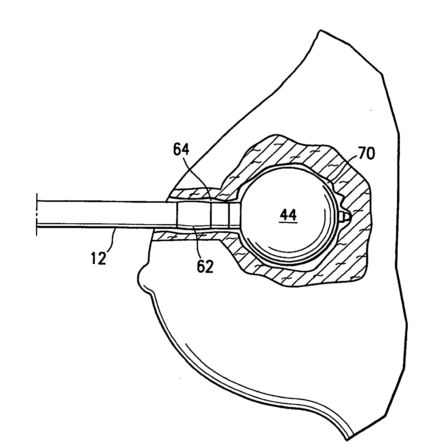
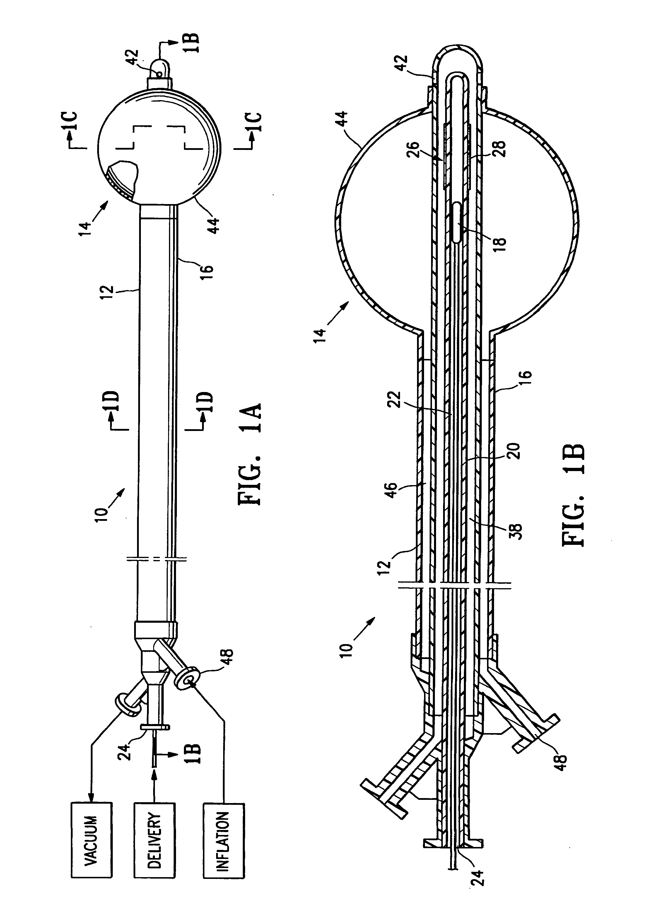
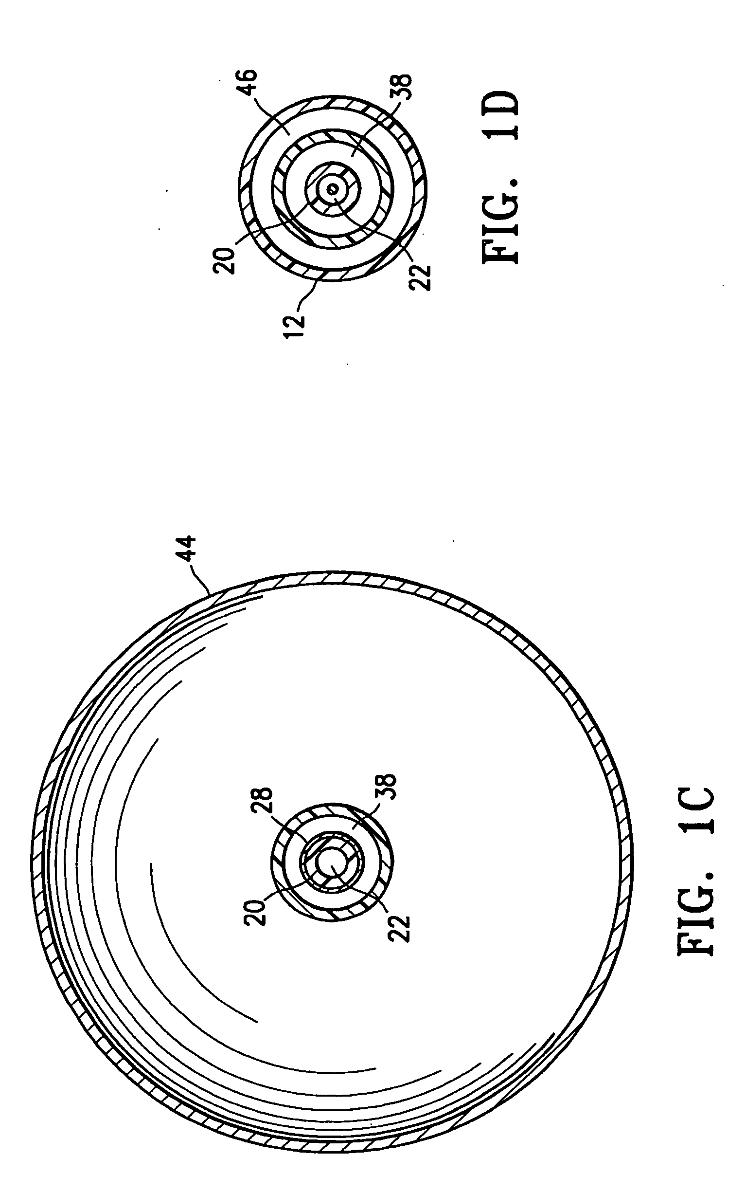
[0052]The present invention provides devices and methods for treatment of a patient's body cavity or other intracorporeal site. For example, devices and methods having features of the invention are used to deliver treatment into a biopsy site or into a cavity or site left after removal of cancerous tissue from the patient's body.

[0053]As shown in FIGS. 1A-1D a tissue treating device 10 embodying features of the invention includes an elongated shaft 12 with a treatment location 14 in a distal portion 16 of the elongate shaft 12. The treatment location 14 includes a source for a treatment agent such as a radiation source 18 which has a push rod 20 for advancing the source within the device. The elongate shaft 12 has a delivery lumen 22 which leads to treatment location 14 for advancement of the radiation source 18 to the treatment location. The elongated shaft 12 also includes a delivery port 24 in fluid communication with the delivery lumen 22 through which the radiation source 18 is...


PUM


Abstract

Devices and methods are disclosed for treatment to tissue surrounding a body cavity or other intracorporeal site, such as after removal of tissue, e.g. cancer. Such a device includes a treatment location on a distal portion of the device with one or more radiation shielding components that partially encircle a radiation source at the treatment location to control emitted radiation from the radiation source. The device minimizes radiation damage to healthy tissue surrounding the body cavity or other site while irradiating tissue not shielded by the radiation shielding components. A device embodying features of the invention can include a sealing member at a location on a shaft of the device proximal to a treatment location to seal the passageway leading to the body cavity.

Description

RELATED APPLICATIONS[0001]This application is a continuation of application Ser. No. 11 / 593,678, filed Nov. 6, 2006, now U.S. Pat. No. 7,517,310 which is a continuation-in-part and claims priority to application Ser. No. 11 / 283,236 filed on Nov. 18, 2005, now U.S. Pat. No. 7,413,539, and to provisional application Ser. No. 60 / 774,266 filed Feb. 16, 2006; Ser. No. 60 / 819,920 filed Jul. 11, 2006, and Ser. No. 60 / 819,919, filed on Jul. 11, 2006, all of which are incorporated herein by reference in their entirety.FIELD OF THE INVENTION[0002]This invention relates generally to the fields of medical treatment devices and methods. In particular, the invention relates to devices and methods for treating tissue surrounding a body cavity, such as a site from which cancerous, pre-cancerous, or other tissue has been removed.BACKGROUND OF THE INVENTION[0003]In diagnosing and treating certain medical conditions, it is often desirable to perform a biopsy, in which a specimen or sample of tissue is...

Claims


Application Information

Patent Timeline
IPC IPC(8): A61M36/04
CPCA61B2017/3419A61N2005/1005A61N5/1015
Inventor LUBOCK, PAULJONES, MICHAEL L.
Owner HOLOGIC INC
Why Eureka
Try Eureka