Processor for endoscope and endoscope system

a technology of endoscope and processor, which is applied in the direction of coupling device connection, ignition automatic control, instruments, etc., can solve the problems of endoscope damage, endoscope size increase, endoscope damage, etc., to prevent damage, image sensor damage, and prevent damage

Inactive Publication Date: 2009-08-20
FUJIFILM CORP
View PDF10 Cites 67 Cited by
  • Summary
  • Abstract
  • Description
  • Claims
  • Application Information

AI Technical Summary

Benefits of technology

[0016]According to the present invention, the output of the drive signals and power supply are stopped in this order in response to detection of the start of removal of the endoscope connector. Thereby, the image sensor is prevented from damage when the endoscope is removed from the processor in a state that the image sensor is driven. In addition, since it is not necessary to modify the existing connectors of the endoscope and the processor, additional cost to develop new connectors for preventing the damage of the image sensor is not necessary. Thus, the CCD of the existing endoscopes is also prevented from damage.

Problems solved by technology

The endoscope increases in size and weight when a power supply and a drive circuit for the CCD are provided in the endoscope, which makes the endoscope difficult to handle.
However, since a doctor delegates a task to stop the CCD, and is extremely busy in a medical site, the CCD is often left activated and the endoscope is removed while the CCD is still driven.
In such cases, when a line for the power supply is disconnected before a line for the drive signals is disconnected, the drive signal may cause unexpected currents in a circuit of the CCD, and may damage the CCD.
However, a plug connector having pins shorter or longer than the rest of the pins is not commercially available.
Therefore, in order to adopt the configuration described in Japanese Patent Laid-Open Publication No. 2000-092478, it is necessary to customize a plug connector, incurring a substantial amount of cost.
In addition, Japanese Patent Laid-Open Publication No. 2000-092478 does not provide a solution to prevent damage of the conventional endoscope with the ordinary plug connector having the pins of the same length.

Method used


Image

  • Processor for endoscope and endoscope system
  • Processor for endoscope and endoscope system
  • Processor for endoscope and endoscope system

Examples


Embodiment Construction

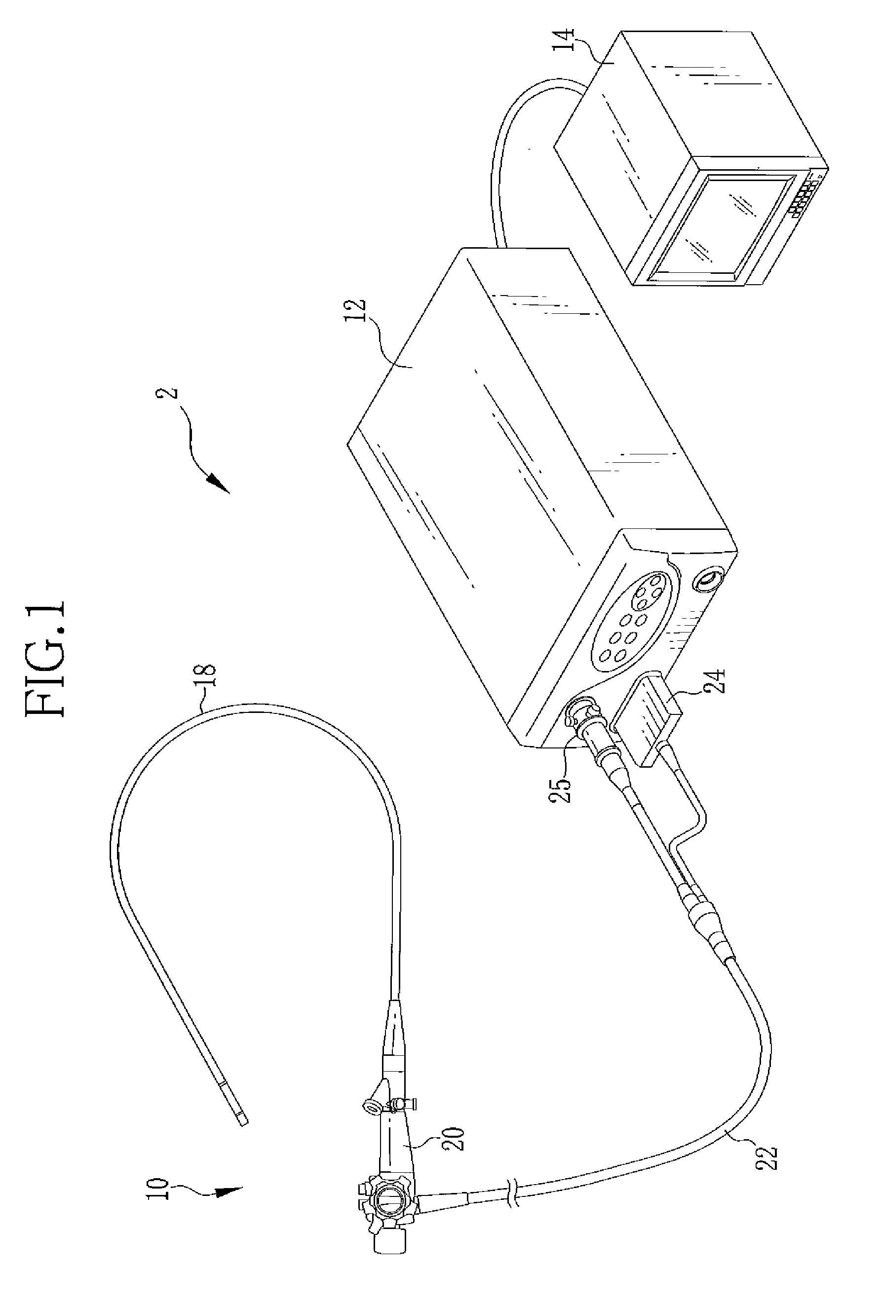
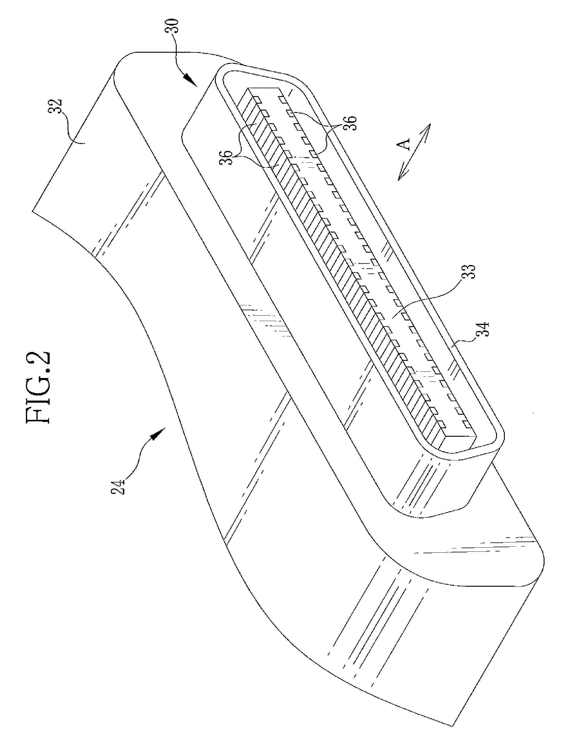
[0027]In FIG. 1, an endoscope system 2 includes an electronic endoscope (hereinafter may simply be referred to as endoscope) 10, a processor 12, and a monitor (display device) 14. Images of a body cavity of a patient are taken using the endoscope 10. The processor 12 generates endoscopic images. The monitor 14 displays the endoscopic images. The endoscope 10 has an insertion section 18, an operating section 20, and a universal cord 22. The insertion section 18 is inserted into the body cavity of the patient. The operating section 20 is connected to a base end portion of the insertion section 18, and hand-operated. The universal cord 22 extends from the operating section 20. The processor 12 is integrated with a light source for illuminating the body cavity. At an end of the universal cord 22 on the opposite side of the operating section 20 are provided a first control connector (endoscope connector) 24 and a first light source connector 25. The first control connector 24 is used for...


PUM

PropertyMeasurementUnit
electricallyaaaaaaaaaa
poweraaaaaaaaaa
mechanical displacementaaaaaaaaaa

Abstract

An electronic endoscope is detachably connected to a processor via a first control connector and a second control connector. Contacts provided at side ends of the flat-shaped second control connector are connected to a CPU. The CPU detects start of removal of the first control connector in response to a change in voltage of one of ports, to which the contacts are connected, from low to high. When the CPU detects the start of the removal, drive signals from a CCD driver to a CCD is stopped. Then, power supply from a power supply section to the CCD is stopped.

Description

FIELD OF THE INVENTION[0001]The present invention relates to a processor for an endoscope, which provides a drive signal and supplies power to an image sensor provided in the endoscope, and an endoscope system constituted of an endoscope and this processor for an endoscope.BACKGROUND OF THE INVENTION[0002]An endoscope system is constituted of an endoscope (scope) and a processor. The endoscope is used for taking images inside a body cavity. The endoscope is detachably connected to the processor via a connector. The processor performs image processing to image data transmitted from the endoscope, and outputs the image data to a display. The endoscope has an image sensor such as a CCD at a distal tip of an insertion section that is inserted in a body cavity. The endoscope increases in size and weight when a power supply and a drive circuit for the CCD are provided in the endoscope, which makes the endoscope difficult to handle. For this reason, it is preferred to provide the power sup...

Claims


Application Information

Patent Timeline
Patent Type & Authority Applications(United States)
IPC IPC(8): A61B1/04G05F3/00
CPCA61B1/045A61B1/00128A61B1/00124G02B23/2484
Inventor HIGUCHI, MITSURU
Owner FUJIFILM CORP
Why Eureka
Try Eureka