
Process and device for diagnostic and maintenance operations of aircraft

Active Publication Date: 2009-08-20
AIRBUS OPERATIONS SAS
View PDF14 Cites 14 Cited by
  • Summary
  • Abstract
  • Description
  • Claims
  • Application Information

AI Technical Summary

Benefits of technology

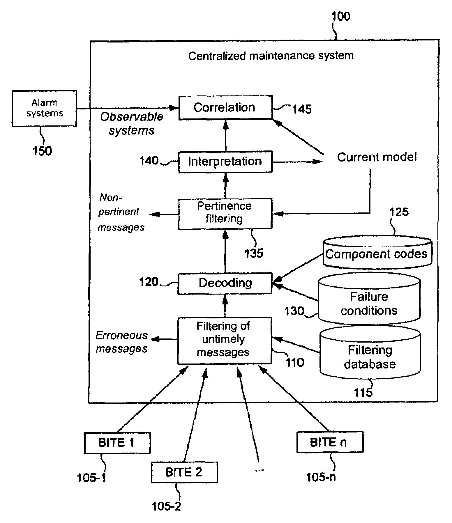
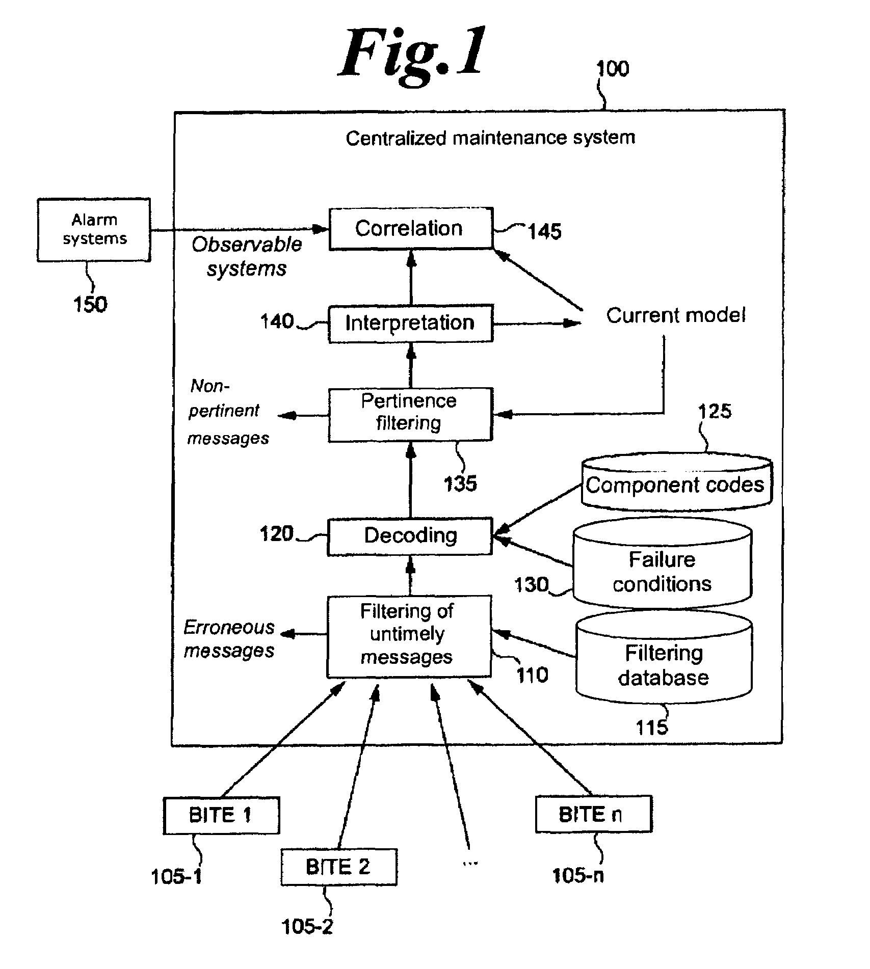
[0021]In this way the method according to the invention makes it possible to filter out the received messages considered to be valid but that have contents judged to be non-pertinent.
[0023]In this way the method according to the invention makes it possible to filter the received messages more precisely, by taking into account the nature of the detected failure and the instant at which it was detected or the instant at which it occurred.
[0026]Advantageously, the said at least one received message comprises at least one reference to the element that transmitted the said at least one received message, and the said filtering step comprises a step of analyzing the said at least one received message to determine the validity of the said received message, the said analysis step being based on the said at least one reference and on at least one parameter of the said system. In this way, the method according to the invention makes it possible to filter out the invalid messages and the non-pertinent messages.

Problems solved by technology

The filtering operations performed today by the centralized maintenance system generally consist in suppressing untimely messages, considered to be unreliable.
However, because the diagnostic assistance systems are increasingly interconnected and becoming increasingly complex, correlation is becoming increasingly difficult.
In addition, by virtue of the proliferation of transducers used, the complexity of the measures taken and the increase of calculating powers, the number and variety of messages generated by the integrated test and diagnostic equipment items have greatly increased.
Consequently, although the diagnostics can be refined, they are more difficult to understand.
Thus, despite the functions of filtering out untimely messages, the correlation functions must consider a large number of messages, posing performance problems.

Method used


Image

  • Process and device for diagnostic and maintenance operations of aircraft
  • Process and device for diagnostic and maintenance operations of aircraft
  • Process and device for diagnostic and maintenance operations of aircraft

Examples


Embodiment Construction

[0034]In the description hereinafter, the following propositional logic operators are used,

[0035]̂ represents the conjunction “and”;

[0036]v represents the disjunction “or”; and

[0037] represents the material implication.

[0038]The propositions are represented by upper-case letters (A, B, . . . ), with indices if necessary. The lower-case letters (t, u, . . . ) represent instants. The time intervals are denoted by the letters I and J, with indices if necessary.

[0039]The messages transmitted by the integrated test and diagnostic equipment items have the form here of (F, I), where F is a logical proposition that may be true or false at each instant and I is a time interval. The message (F, I) means that: “F is true for every instant t belonging to the interval I (t ∈I)”.

[0040]According to the invention, all the messages that do not provide any supplementary information are filtered according to the following logico-temporal reasoning principle by considering that the information items (F...


PUM


Abstract

The object of the invention is a method and a device for filtering diagnostic messages obtained from a plurality of elements of a system, each of these elements comprising diagnostic means capable of detecting a failure and of transmitting a message comprising at least one failure indication. The state of at least certain elements of the said plurality of elements is represented by a model of state. After at least one failure message has been received, this message is filtered according to the failure indication that it contains and according to the model of state. In response to the filtering step, the model of state is updated according to the failure indication or the message is rejected. The filtering step is advantageously based on a propositional logic mechanism.

Description

TECHNICAL FIELD OF THE INVENTION[0001]The present invention relates in general to maintenance operations on aircraft and more particularly to an improved method and device for diagnostic and maintenance operations capable of efficiently integrating diagnostic data obtained from different elements.PRIOR ART[0002]First-level maintenance of aircraft, or in other words the entirety of direct interventions (not including shop repairs), primarily comprises corrective actions aimed at replacing or repairing failing aircraft components or components in the course of degradation, scheduled inspections, generally periodic, and preventive actions, such as replacement of equipment items having limited useful life.[0003]The corrective actions are based in particular on knowledge of the state of the aircraft, obtained in particular from crew reports, on-board diagnostic systems and inspections conducted during the scheduled checkups.[0004]The on-board diagnostic systems have a two-level architect...

Claims


Application Information

Patent Timeline
IPC IPC(8): G05D1/00G06N7/00
CPCG05B23/0272G05B2219/13G06F11/0739G06F11/079G06F11/0781G06F11/0784G06F11/0748G05B2223/06
Inventor BERNARD, DENYSBORDRY, CHRISTOPHE
Owner AIRBUS OPERATIONS SAS
Learn More