Collision safety control device

Active Publication Date: 2009-08-20
ISUZU MOTORS LTD
View PDF8 Cites 0 Cited by
  • Summary
  • Abstract
  • Description
  • Claims
  • Application Information

AI Technical Summary

Benefits of technology

[0015]It is accordingly an object of the present invention to provide a collision safety control device having improved a reliability of airbag deployment at an offset collision or the like without providing a contact part with a cab.
[0017]Namely, according to the present invention, a ground wire of a collision safety control device for a collision safety equipment such as an airbag is ensured over a plurality of wire portions, so that even at an offset collision it becomes possible to ensure at least one ground wire portion or line without being disconnected.
[0020]As noted above, while the collision safety control device is required to be normally operated even when the vehicle body is damaged by a collision, the collision safety control device according to the present invention can highly improve its operation reliability by providing a plurality of ground wire portions.
[0021]Also, since it is rare that at an offset collision the frame is broken both on the right and the left sides thereof, two of the ground wire portions are mutually separated by more than the width of the frame, whereby even if one ground wire portion is disconnected at the collision, it becomes possible to securely reserve the remaining ground wire portion(s) to be used, resulting in a very low possibility of the original collision safety function being impaired.
[0022]Additionally, by connecting the ground wire separately to the cab and the frame, it becomes possible to connect the ground wire to the frame without extending a harness having a possibility of disconnection.

Problems solved by technology

Also, with such an incomplete ground wiring, a controller inside the unit case can be damaged by a lightning strike.

Method used


Image

  • Collision safety control device
  • Collision safety control device
  • Collision safety control device

Examples


embodiment

[1]: FIGS. 1-3

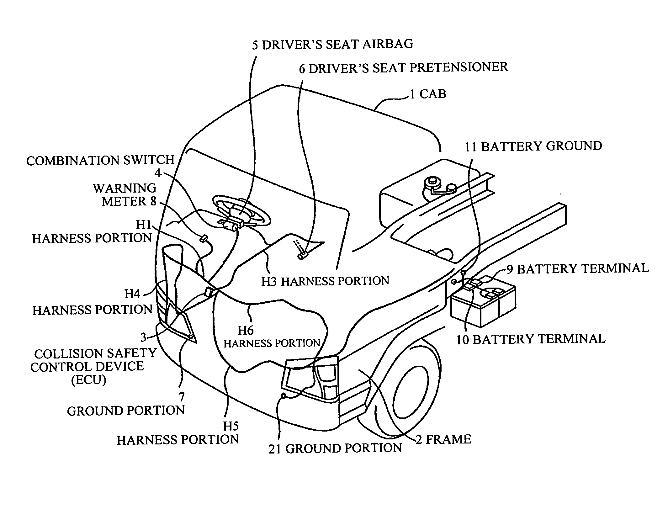
[0029]FIG. 1 shows a ground wiring structure in an embodiment [1] of a collision safety control device according to the present invention, which is different from the prior art shown in FIG. 5 in that a harness portion H6 is further connected to the harness portion H1 and a ground portion 21 is provided at one end of the harness portion H6 and connected to the left side (front passenger's seat side) of the vehicle body frame 2.

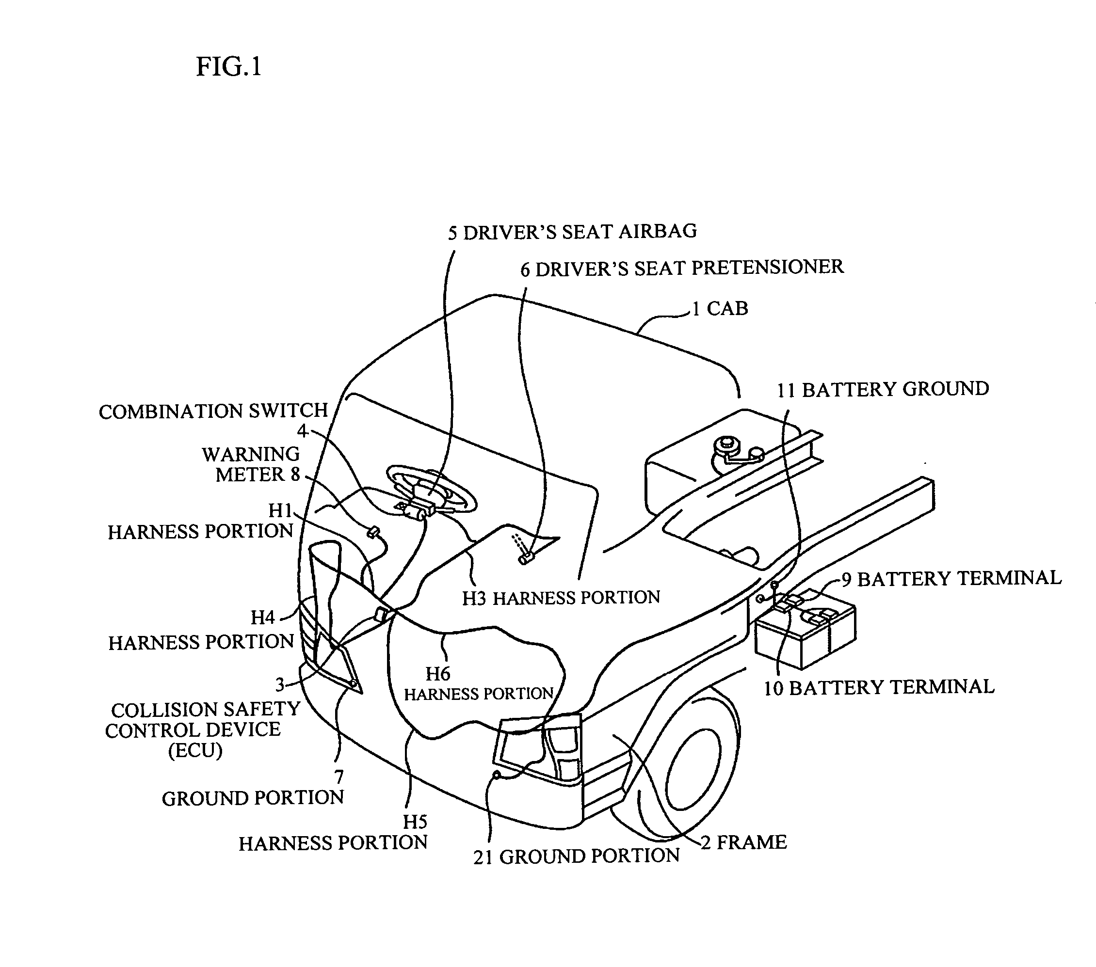
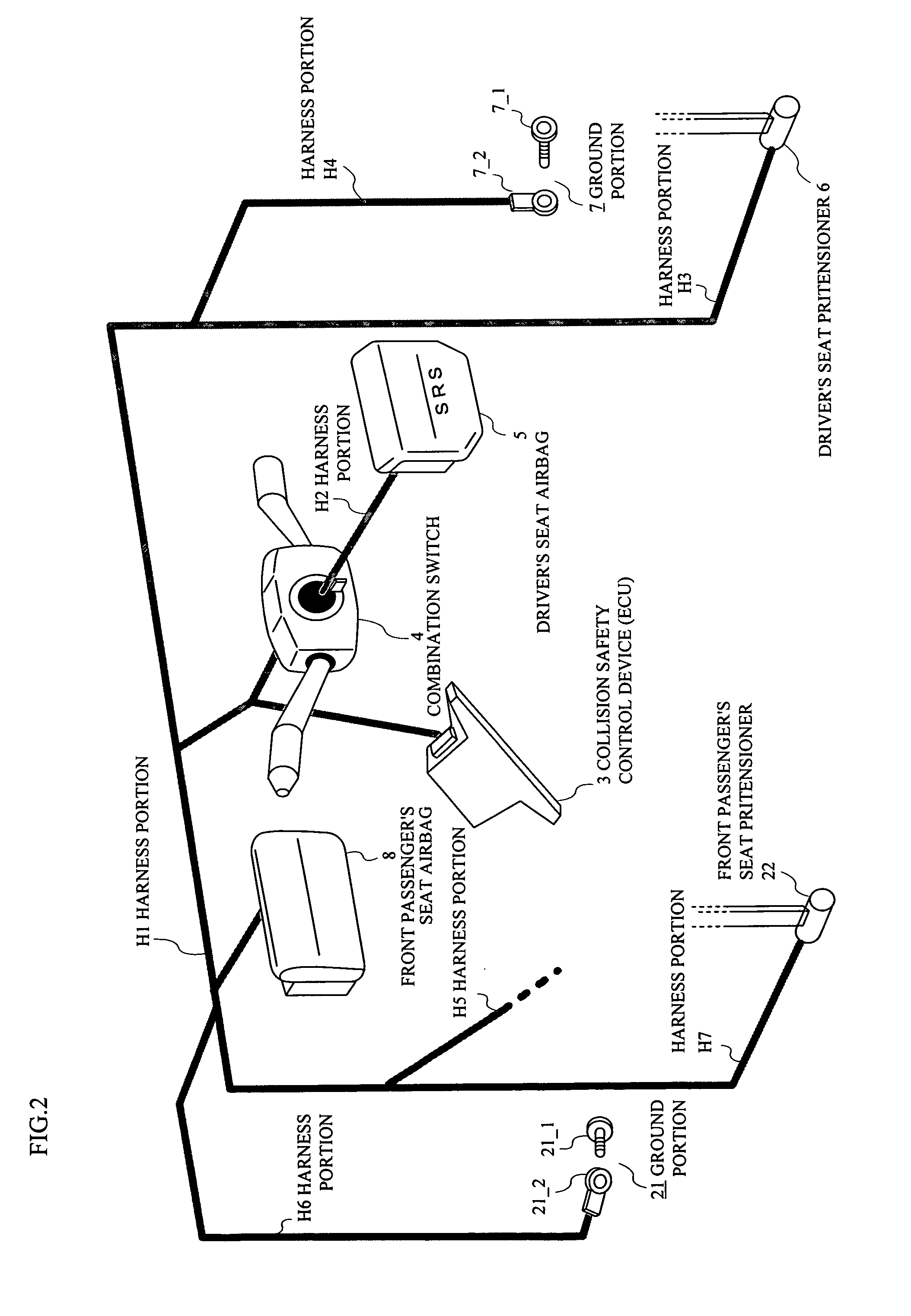
[0030]FIG. 2 shows conceptually in an easily understood manner a ground wiring structure in the collision safety control device of the present invention shown in FIG. 1.

[0031]Namely, the collision safety control device 3 is connected to the ground portion 7 secured to the right side of the vehicle body frame 2 with the harness portions H1 and H4 (forming a ground wire) as well as to the ground portion 21 secured to the left side of the vehicle body frame 2 with the harness portions H1 and H6 (forming a ground wire), where the ground portion 7 is ...


PUM


Abstract

For achieving a collision safety control device having improved a reliability of airbag deployment at an offset collision or the like without providing a contact part with a cab, a ground wire is connected to a plurality of portions of a vehicle body frame, in which two of the plurality of portions may be mutually separated by more than a width of the frame and the ground wire may comprise a first portion connecting from the collision safety control device to the cab and a second portion connecting from the cab to the frame.

Description

CROSS-REFERENCE TO RELATED APPLICATION[0001]This application is a continuation of International Application PCT / JP2007 / 69480 filed on Oct. 4, 2007, the contents of which are herein wholly incorporated by reference.BACKGROUND OF THE INVENTION[0002]1. Field of the Invention[0003]The present invention relates to a collision safety control device, and in particular to a ground or earth wiring structure of the collision safety control device controlling actions of a collision safety equipment such as an SRS (Supplement Restraint System) airbag or a seat belt pretensioner etc.[0004]2. Description of the Related Art[0005]Prior art ground wiring structure of such a collision safety control device takes advantage of a cab 1 and a frame 2 in a cab over engine truck as shown in FIG. 5, in which the collision safety control device (ECU) 3 is connected to a combination switch 4 and a driver's seat airbag 5 with harness portions H1 and H2, and is further connected to a driver's seat pretensioner ...

Claims


Application Information

Patent Timeline
IPC IPC(8): B60R21/01
CPCB60R21/013B60R2021/0023B60R21/0173
Inventor SUZUKI, KIKUOMIKAWA, ATSUSHI
Owner ISUZU MOTORS LTD
Why Eureka
Try Eureka