
Animal euthanasia by electrocution

Inactive Publication Date: 2009-08-27
DENICOURT MARTINE +1
View PDF6 Cites 5 Cited by
  • Summary
  • Abstract
  • Description
  • Claims
  • Application Information

AI Technical Summary

Benefits of technology

[0025]Preferably the independent electrical supply control unit comprises a battery such as a 12V or 24V battery and a transformer for receiving the current from the battery and for generating the required voltage to be applied to the electrodes. However the use of a battery is not essential and the device may be operated solely by current from a mains supply. In this case, the mains supply is separated from the current supplied across the electrodes by a transformer so that the euthanizing current is isolated from the mains supply. This avoids any current being lost by leaking to ground and provides increased safety for the worker.
[0079]The electrical generator with a built-in transformer and the isolation of the mains hydro circuit insure the transmission of the voltage without loss of current, which permits a safe manipulation for the user.

Problems solved by technology

However this is not the same process as euthanasia where the animal is required to be killed, generally in circumstances where the meat cannot be used and the carcass must be disposed of.
Most official methods proposed to the farmers for euthanasia cause a cranial traumatism.
This method even though its acceptable for the well-being of the animal but is traumatizing for the workers in view of the blood flow.
However this is not recognized and is considered dangerous.
The jumper cables are painful to the animal and not easy to attach;
The direct connection in the electrical circuit without any element of protection and where the animal is unrestrained is dangerous for the user;
The results of euthanizing by electrocution in this manner are uncertain in some cases failing to cause immediate death leaving the animal to suffer.

Method used


Image

  • Animal euthanasia by electrocution
  • Animal euthanasia by electrocution
  • Animal euthanasia by electrocution

Examples


Embodiment Construction

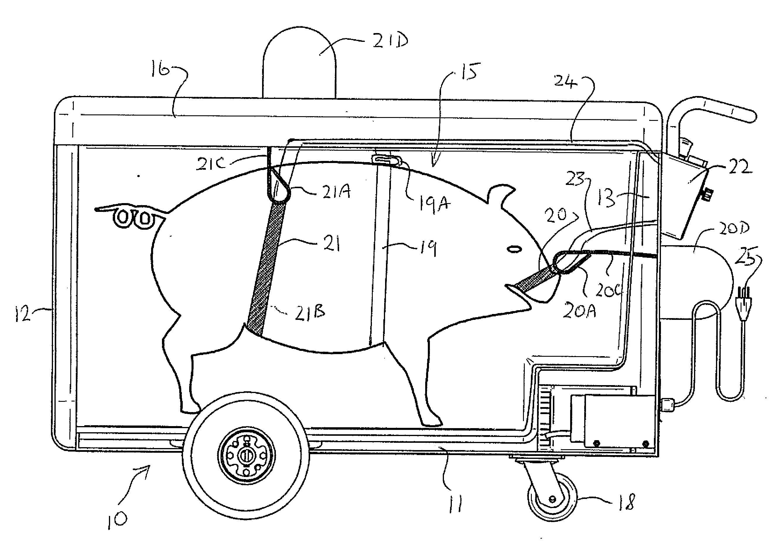
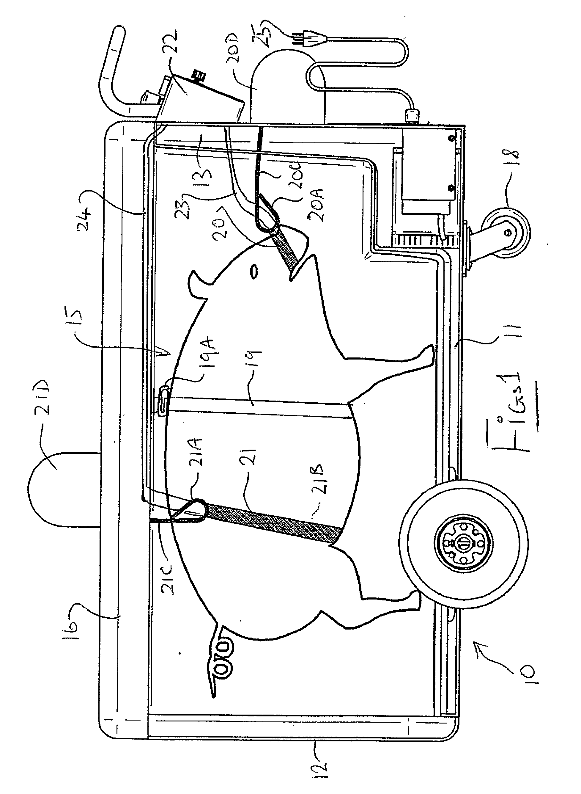
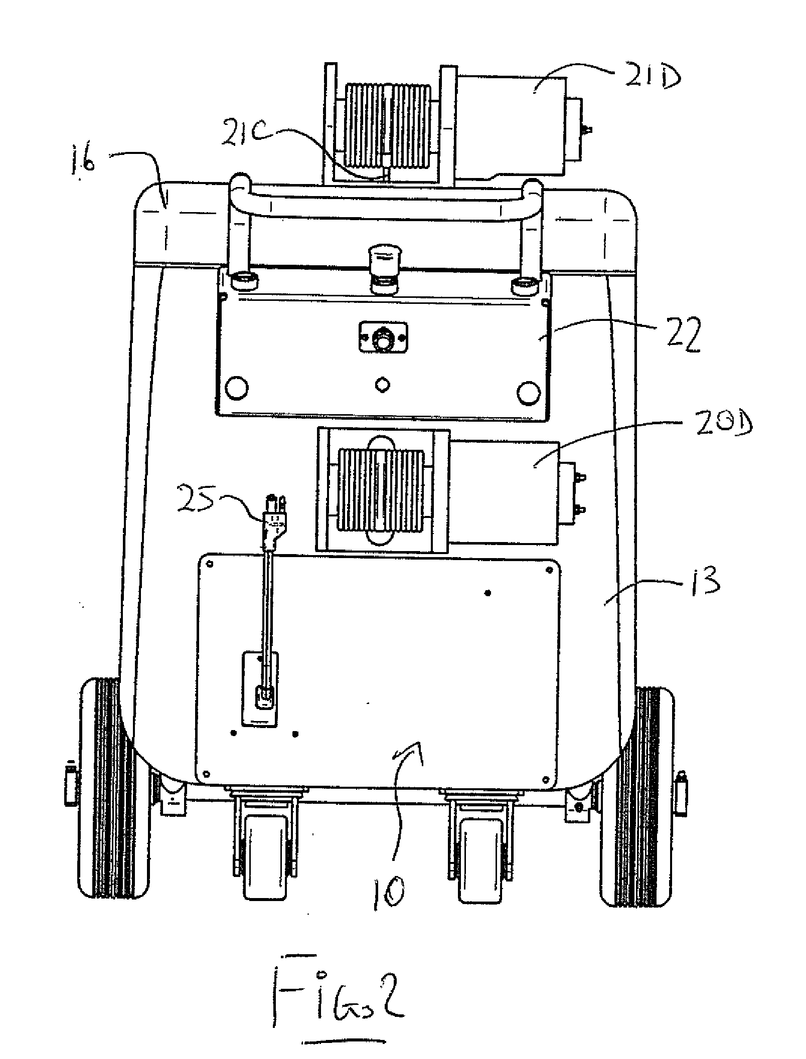
[0089]The apparatus shown in FIGS. 1 and 2 for euthanasia of animals includes a container 10 with base 11 and side walls 12 and 13 for the animal 14 during electrocution. An optional folding loading ramp can be included for the animals to enter from floor level onto the base. The container 10 has a closed top 15 to ensure safety of user. The container includes a longitudinally extending support structure 16 for providing support for the animal during the procedure. The container including the base and side walls can be formed of an electrically insulating material so that the animal is isolated from the workers during the procedure.

[0090]In order that the container can be readily tailored to match the size of the animal, additional panels can be provided as partition walls or a supplementary floor so that the animal even if small is properly confined.

[0091]The container has a door preferably at one end 12 for the animal to be easily lead into the container. The container is carried ...


PUM


Abstract

Apparatus for euthanasia of animals by electrocution includes a container on wheels formed of an electrically insulating material and a rechargeable 12V battery powered control unit carried on the container for supplying through a transformer AC electric current at 110V to electrodes through insulated electrical supply cables. The first electrode is a conductive wire forming a loop arranged to be wrapped around the snout and through the mouth of the animal. The second electrode is a belt shaped and arranged to wrap around the belly of the animal at a position just in front of the rear legs. An alternative second electrode may be a rectal probe. Each of the electrodes is attached to a winch by which it can be pulled to apply tension electrode during the electrocution. In a second arrangement the control unit and the electrodes are arranged to be hand carried to the animal.

Description

[0001]This application claims the benefit under 35 U.S.C. 119 of Provisional Application No. 61 / 025,269 filed Jan. 31, 2008.[0002]This invention relates to an apparatus for use in animal euthanasia by electrocution.BACKGROUND OF THE INVENTION[0003]Many patented proposals have been made for the use of electricity to stun animals in a slaughterhouse where the animal must be stunned for humanitarian reasons prior to killing by other means for use of the meat. However this is not the same process as euthanasia where the animal is required to be killed, generally in circumstances where the meat cannot be used and the carcass must be disposed of.[0004]There are a number of patents on techniques for euthanasia which provide many different techniques, but electrocution is not proposed.[0005]Most official methods proposed to the farmers for euthanasia cause a cranial traumatism. This method even though its acceptable for the well-being of the animal but is traumatizing for the workers in vie...

Claims


Application Information

Patent Timeline
IPC IPC(8): A01M23/38A01K15/04
CPCH05C1/02A22B3/06
Inventor DENICOURT, MARTINEKLOPFENSTEIN, CHRISTIAN
Owner DENICOURT MARTINE
Learn More