Door with closing profile and integrated ventilation

a technology of door and window body, applied in the field of closing profiles, can solve the problems of vacuum effect, disadvantage, high pressure to be exerted to open the door, etc., and achieve the effect of reducing the pressure needed to open the door

Inactive Publication Date: 2009-08-27
INDOOR COLLECTION NV
View PDF13 Cites 12 Cited by
  • Summary
  • Abstract
  • Description
  • Claims
  • Application Information

AI Technical Summary

Benefits of technology

[0011]It is a first aim of the invention to provide a door assembly with a closing profile provided for releasably maintaining a door in a closed position, with which gaps between the door and the adjacent member of the door assembly can be avoided and simultaneously the pressure needed to open the door can be reduced.

Problems solved by technology

However, practice has shown that since the concave recess snugly fits in the convex projection, the pressure which has to be exerted to open the door is very high.
This reduces the pressure needed for opening the door, but enables light to shine through, which may be considered a disadvantage.
In general, sealing the gaps between the door and the adjacent member may cause two problems.
A first problem is that a vacuum effect takes place in case the door is placed between two adjacent rooms with rather small dimensions.
Because of this vacuum effect a higher force has to be exerted on the door to open it, which is not desired.
A second problem is that no air can flow from one room to another, which may result in an unhealthy climate inside one of the rooms.
This ventilation grid can be seen from outside and has a negative effect on the aesthetic appearance of the door.

Method used


Image

  • Door with closing profile and integrated ventilation
  • Door with closing profile and integrated ventilation
  • Door with closing profile and integrated ventilation

Examples


Embodiment Construction

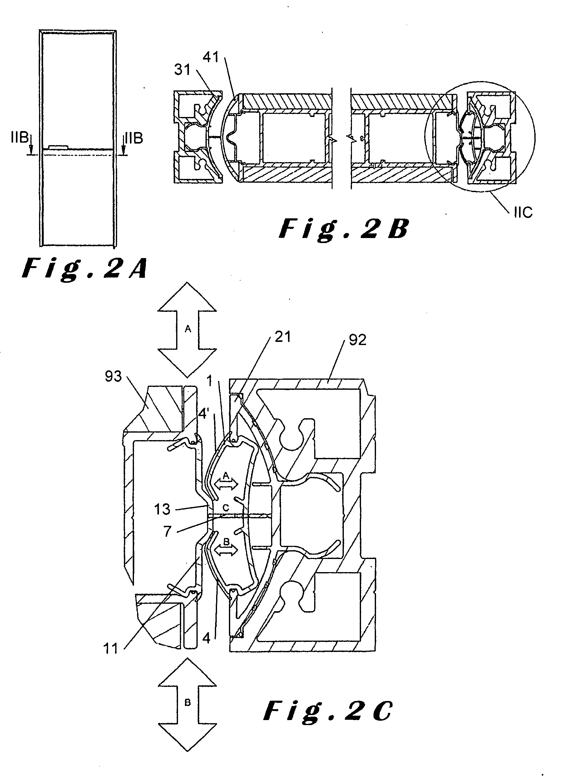
[0065]The doors shown in the figures are rotatable about a vertical axis and fit in wall openings. The wall openings may be provided with door frames. The doors may be rotatable in one or in both directions over for example 90°. The doors each time comprise two vertical edges and two horizontal edges. The rotation axis of each door may be provided near one of its vertical edges or somewhere between its first and second vertical edges, i.e. a centrally rotatable door. In some cases a double door is fitted in the wall opening, i.e. two adjacent doors with adjacent vertical edges, as is shown in FIGS. 4 and 5.

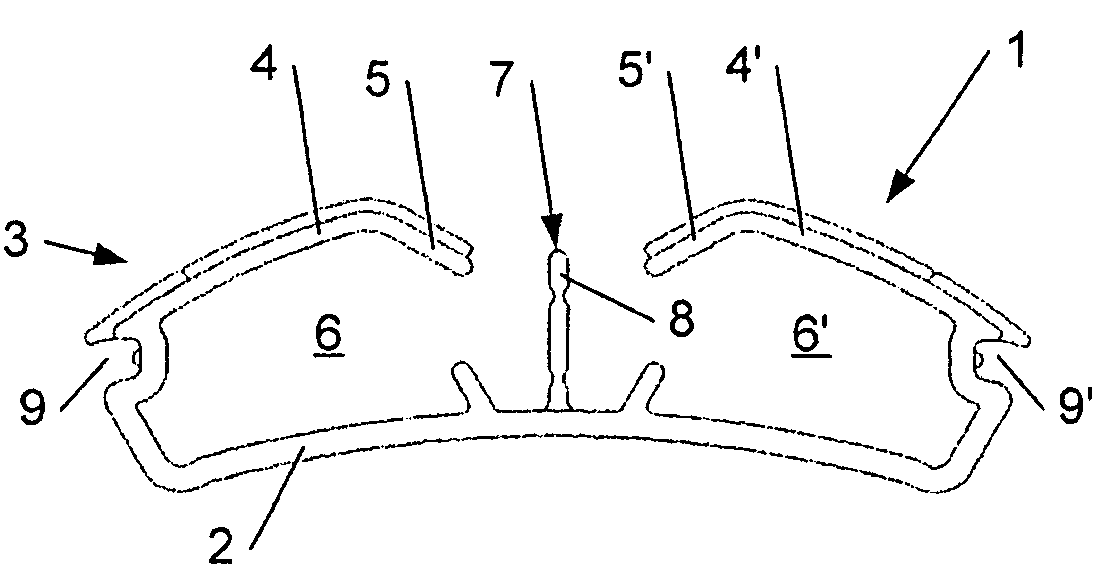
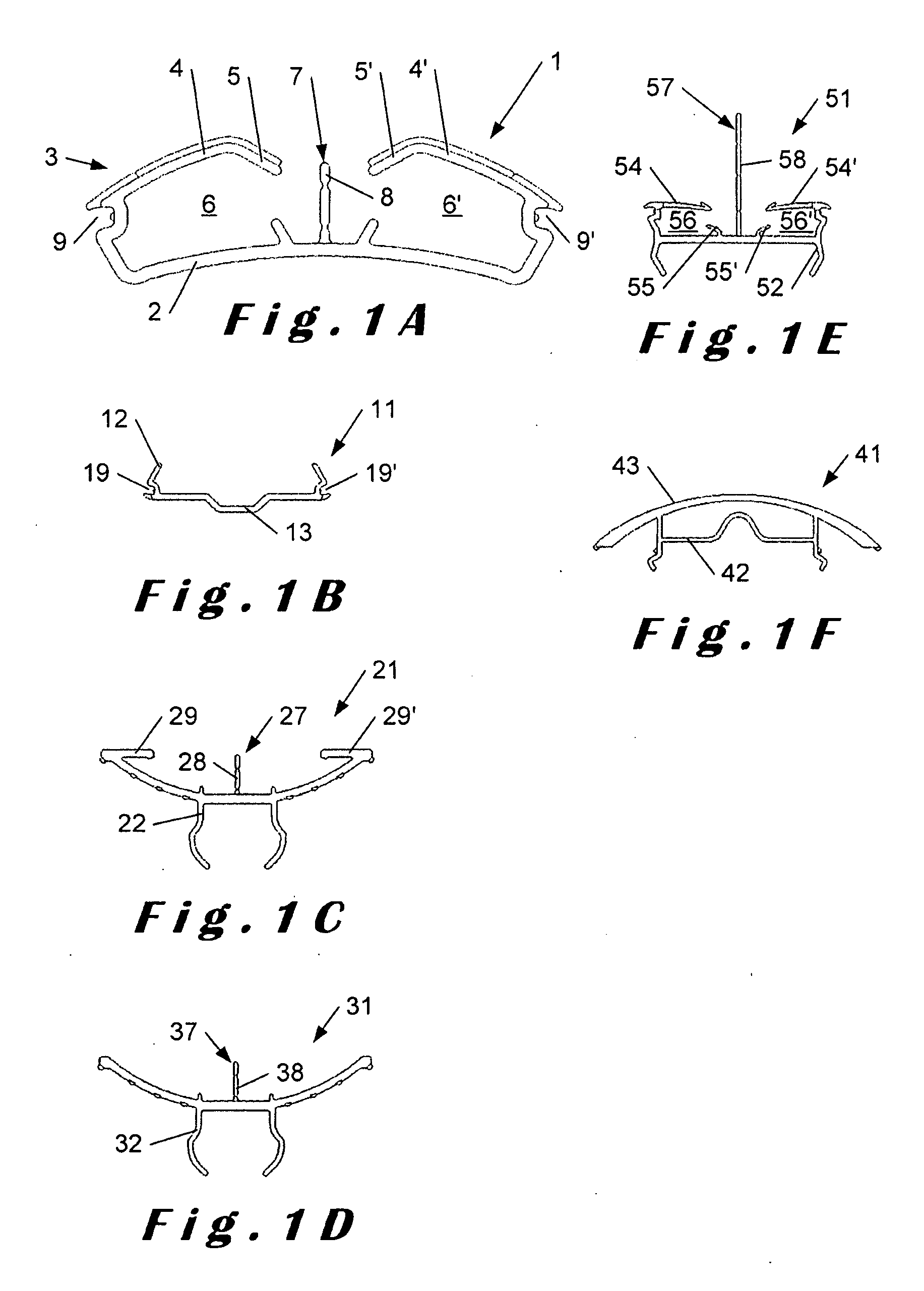
[0066]The closing profile shown in FIG. 1A is applied in each of the cases shown in FIGS. 2-7. The specific area where the closing profile is used is indicated by a circle.

[0067]The closing profile 1 of FIG. 1A comprises a mounting member 2 which is provided for mounting the closing profile 1 to a first door assembly member 92, for example a door frame or a door edge. The closing ...


PUM

PropertyMeasurementUnit
flexibleaaaaaaaaaa
lengthaaaaaaaaaa
axis of rotationaaaaaaaaaa

Abstract

A closing profile for mounting on one of two opposite members of a door assembly, at least one of the opposite members being a rotatable door, the closing profile including a mounting member by means of which the closing profile is mounted to a reveal part of the one member of the door assembly and a flexible member connected to the mounting member, the flexible member being shaped for engaging a complementary edge part on the other member of the door assembly and for releasably maintaining the door in a closed position. The closing profile may have a hollow space between the flexible member and the mounting member to enable the flexible member to deform resiliently towards the mounting member upon opening the door, and the flexible member is preferably longitudinally divided into two wings, each being provided for engaging the complementary edge part and maintaining the closed position in one direction of opening the door, the wings being bendable independently from each other towards the mounting member. A door assembly includes a door and a door frame mountable in a wall opening and a number of circumferential profiles fixable to the door and / or the door frame for optically closing gaps between the door and the wall opening, the door optionally having an oblong grip profile which divides the door into separate door panel segments extending on opposite sides of the grip profile, wherein at least a first of the circumferential profiles and / or the oblong grip profile has an integrated ventilation system and is constructed such that the integrated ventilation system is hidden in the profile and penetration of light therethrough is avoided.

Description

CROSS REFERENCE TO RELATED APPLICATIONS[0001]This application is a continuation-in-part of International Application No. PCT / EP2007 / 060982, filed Oct. 15, 2007, which claims the priority benefit of Belgian Application No. 2006 / 0508, filed Oct. 13, 2006, and Belgian Application No. 2009 / 0119, filed Feb. 26, 2009, all of which are incorporated herein by reference in their entirety.BACKGROUND OF THE INVENTION[0002]1. Technical Field[0003]In a first aspect, the present invention relates to a closing profile provided for mounting on one of two opposite members of a door assembly, at least one of the opposite members being a rotatable door, the closing profile comprising a mounting member by means of which the closing profile is mounted to a reveal part of the one member of the door assembly and a flexible member connected to the mounting member, the flexible member being shaped for engaging a complementary edge part on the other member of the door assembly and for releasably maintaining ...

Claims


Application Information

Patent Timeline
Patent Type & Authority Applications(United States)
IPC IPC(8): E06B7/22E05D15/00
CPCE06B3/90E06B7/02E06B7/22E06B7/2305E06B7/2312
Inventor DRIES, RUDI
Owner INDOOR COLLECTION NV
Why Eureka
Try Eureka