Link for a linear actuator

a linear actuator and link technology, applied in the direction of driving chains, roofs, doors, etc., can solve the problems of increasing manufacturing costs and increasing the number of components required, and achieve the effect of restricting pivoting and simplifying the structur

Active Publication Date: 2009-08-27
MARINE CANADA ACQUISITIONS INC
View PDF20 Cites 11 Cited by
  • Summary
  • Abstract
  • Description
  • Claims
  • Application Information

AI Technical Summary

Benefits of technology

[0007]The link has a simplified structure to restrict pivoting when the link is aligned along a longitudinal aligned along a common longitudinal axis outside the actuator housing.

Problems solved by technology

However, it also increases the number of components required thereby increasing manufacturing costs.

Method used


Image

  • Link for a linear actuator
  • Link for a linear actuator
  • Link for a linear actuator

Examples


Embodiment Construction

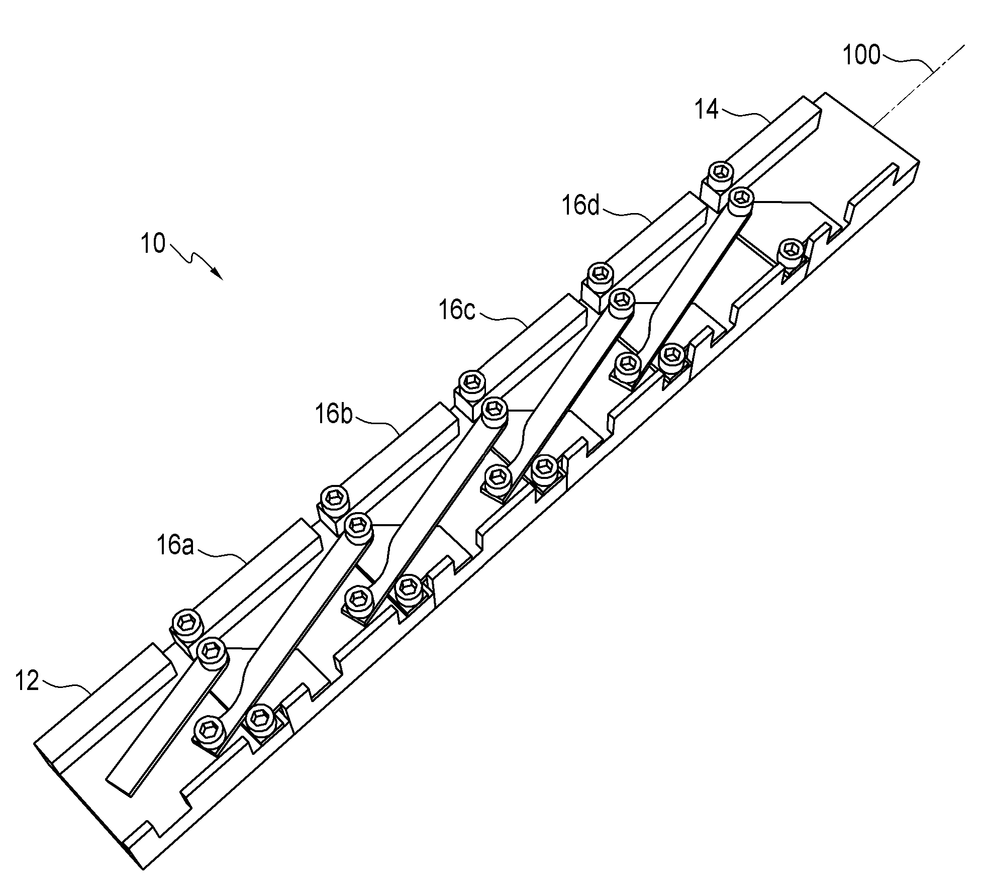
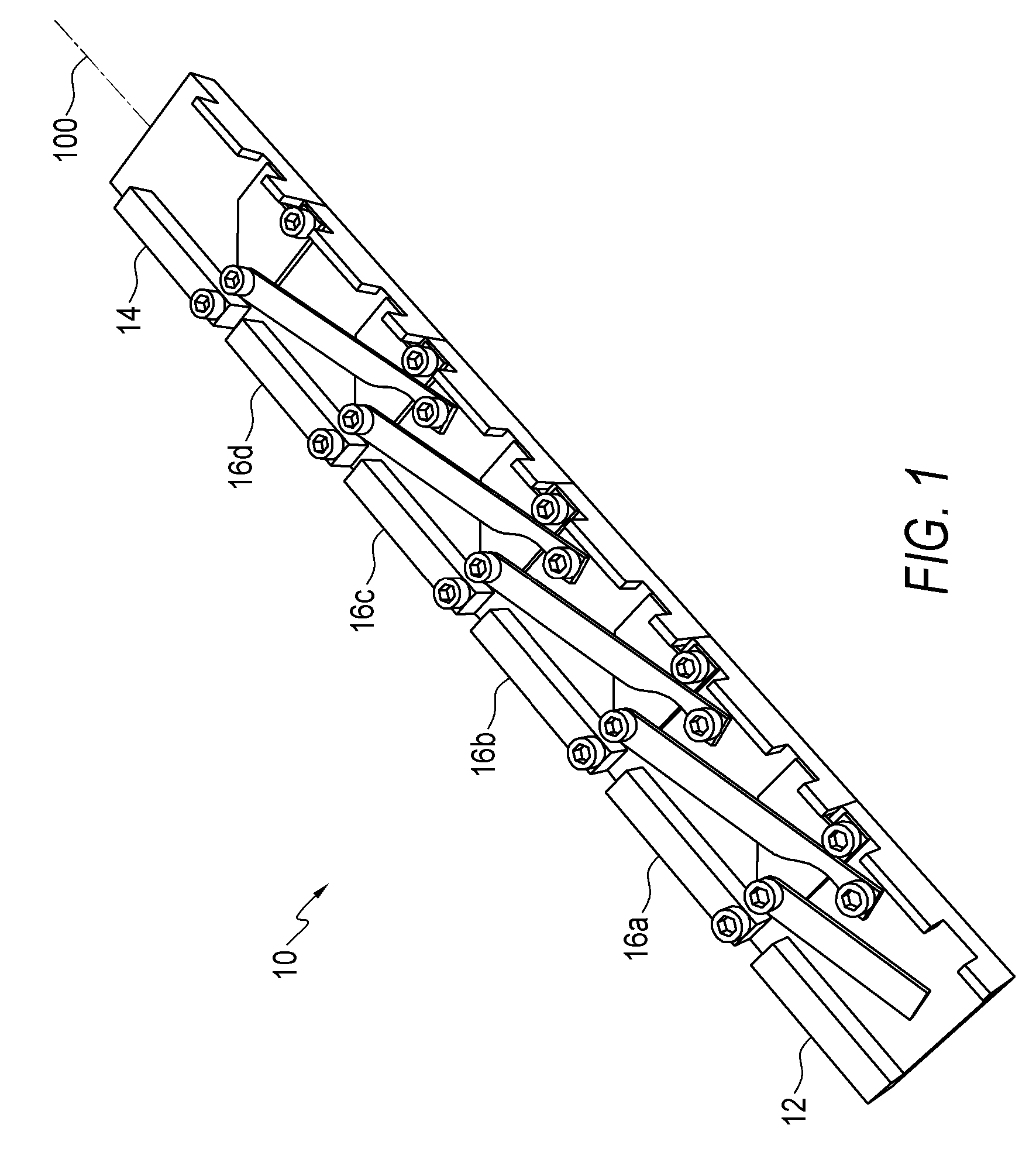
[0017]Referring to the drawings and first to FIG. 1, this shows a chain 10 for use in a linear actuator as shown in FIGS. 6 and 7. Referring back to FIG. 1, the chain comprises a pair of end links 12 and 14, and a plurality of intermediate links 16a, 16b, 16c, and 16d therebetween. The intermediate links 16a, 16b, 16c, and 16d are substantially identical and accordingly only one of the intermediate links 16a is described in detail herein. The end links 12 and 14 are substantially similar the intermediate links 16a, 16b, 16c, and 16d with the general exception that a proximal one of the ends links 12 does not have male connecting means to connect to an adjacent link, and a distal one of the end links 14 does not have female means to connect to an adjacent link. Accordingly, the end links 12 and 14 are not described herein in detail.

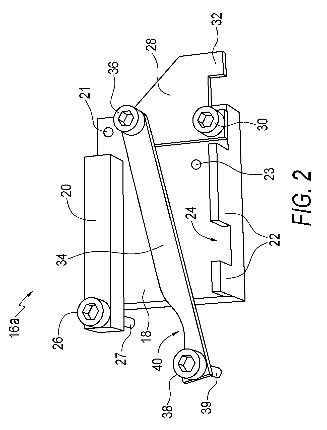
[0018]Referring now to FIG. 2, a first one of the intermediate links 16a is shown in greater detail. The link 16a has a base member 18 which is rectangula...


PUM


Abstract

A link for a chain, which is used in a linear actuator, comprises a base member and a plate pivotably mounted on the base member. An arm extends from the plate. A first connecting means is disposed on a distal end of the arm to connect the link with a first adjacent link. The plate has a protrusion for releasably engaging a second adjacent link. A second connecting means is disposed on the base member to connect the link with the second adjacent link.

Description

CROSS REFERENCE TO RELATED APPLICATION[0001]This application claims the benefit of provisional application 61 / 031,786 filed in the United States Patent and Trademark Office on Feb. 27, 2008, the disclosure of which is incorporated herein by reference and priority to which is claimed pursuant to 35 U.S.C. section 120.BACKGROUND OF THE INVENTION[0002]The present invention relates to a single chain linear actuator and, in particular, to a link for a single chain linear actuator.[0003]Linear actuators having a single extending and retracting chain are well known in the art. Examples of single chain linear actuators are disclosed in International Application No. PCT / DK2004 / 000682 to Andersen et al., and International Application No. PCT / EP2005 / 004449 to Soerensen. The actuator chain comprises a plurality of inter-connected links with each link being pivotably connected to an adjacent link. This allows the chain to be displaced along a curved chain track, or chain path, as the chain is mo...

Claims


Application Information

Patent Timeline
Patent Type & Authority Applications(United States)
IPC IPC(8): F16G13/00
CPCF16G13/20
Inventor SCOTT, JONFETCHKO, ERIC
Owner MARINE CANADA ACQUISITIONS INC
Why Eureka
Try Eureka