Bubble-tolerant micro-mixers

Inactive Publication Date: 2009-08-27
CEQUR SA
View PDF55 Cites 3 Cited by
  • Summary
  • Abstract
  • Description
  • Claims
  • Application Information

AI Technical Summary

Benefits of technology

[0011]This invention relates to simple mixing by laminating layers of fluids together, where a first fluid is merged to a second fluid from two sides, leading to a laminated flow structure of the fluids, a lamination process that may naturally be repeated to increase the number of laminated layers of fluids. The laminated fluids then follow a channel section of such a length, that diffusion ensures a sufficient mixing of the fluids, at least in the ideal situation.
[0013]Based on this, it has now been found that, by suitably widening the inlet of the flow channel dependent on the desired flow rate, it is possible to control the timing of perturbation growth of the liquid film around gas bubbles in the channel, in such a manner that any bubble fragmentation is controlled to bubble lengths only longer than the critical length and thus posing no risk of blocking the capillary.
[0014]The objective of this invention is to create a reliable micro-mixer, where the fluids are laminated and mixed by simple diffusion, without the drawbacks of bubbles affecting the flow rates and thereby the laminations and the mixing.
[0018]at least one second transfer conduit in fluid communication with the second of said fluids, the second transfer conduit having at least two fluid outlets in fluid communication with said first transfer conduit,where each of said outlets of said second transfer conduit is downstream and in fluid communication with the outlet of one of said flow restrictors, and wherein the flow restrictors are bubble-tolerant, being formed to prevent fragmentation of bubbles entering the flow restrictor, into a bubble train consuming the pressure difference between the source and the recipient.

Problems solved by technology

However, if the fluids contain bubbles the flow rates may be affected as described previously, in a way that makes the mixing unpredictable and unreliable.

Method used


Image

  • Bubble-tolerant micro-mixers
  • Bubble-tolerant micro-mixers
  • Bubble-tolerant micro-mixers

Examples


Embodiment Construction

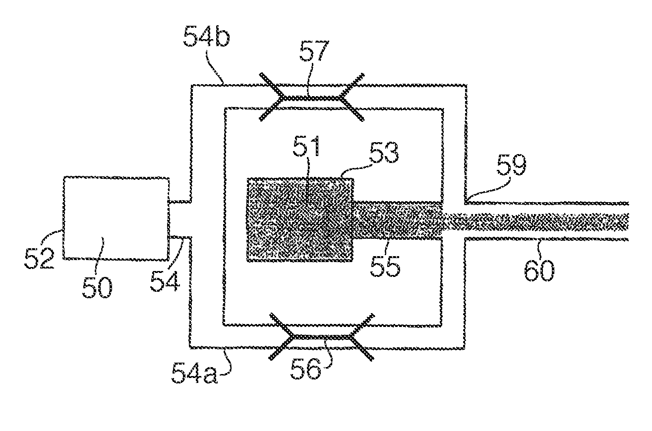
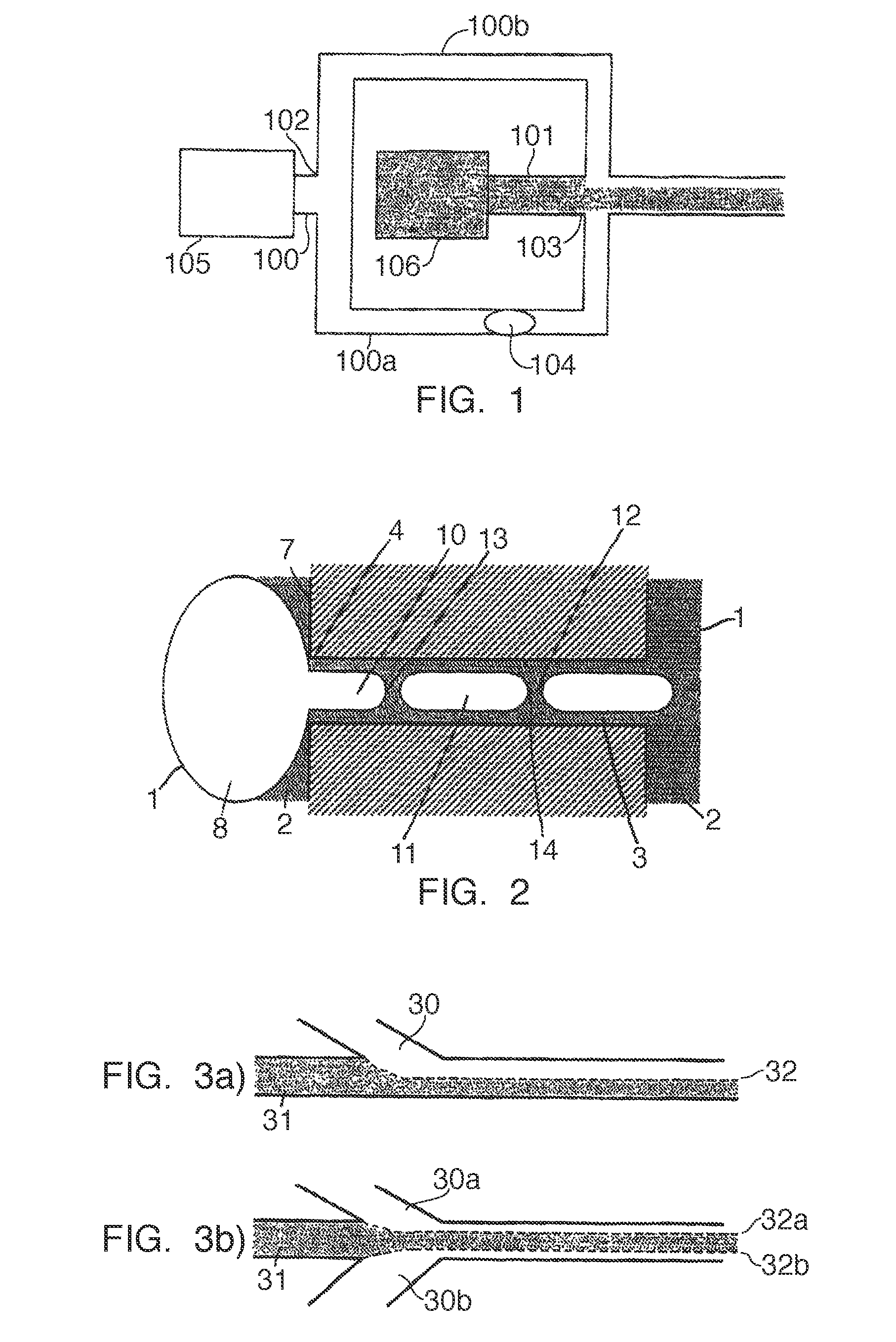
[0026]FIG. 1 illustrates the channel 100 receiving fluid from the reservoir 105, where the reservoir may be an elastomer bladder squeezing out the fluid, it may be a flexible reservoir placed in a pressurized container, or it may be any other means for storing a fluid and creating a flow.

[0027]A second channel 101 is communicating a second fluid from the reservoir 106, reservoir 106 in the preferred embodiment of the invention being identical to the reservoir 105, but this is not essential to the invention.

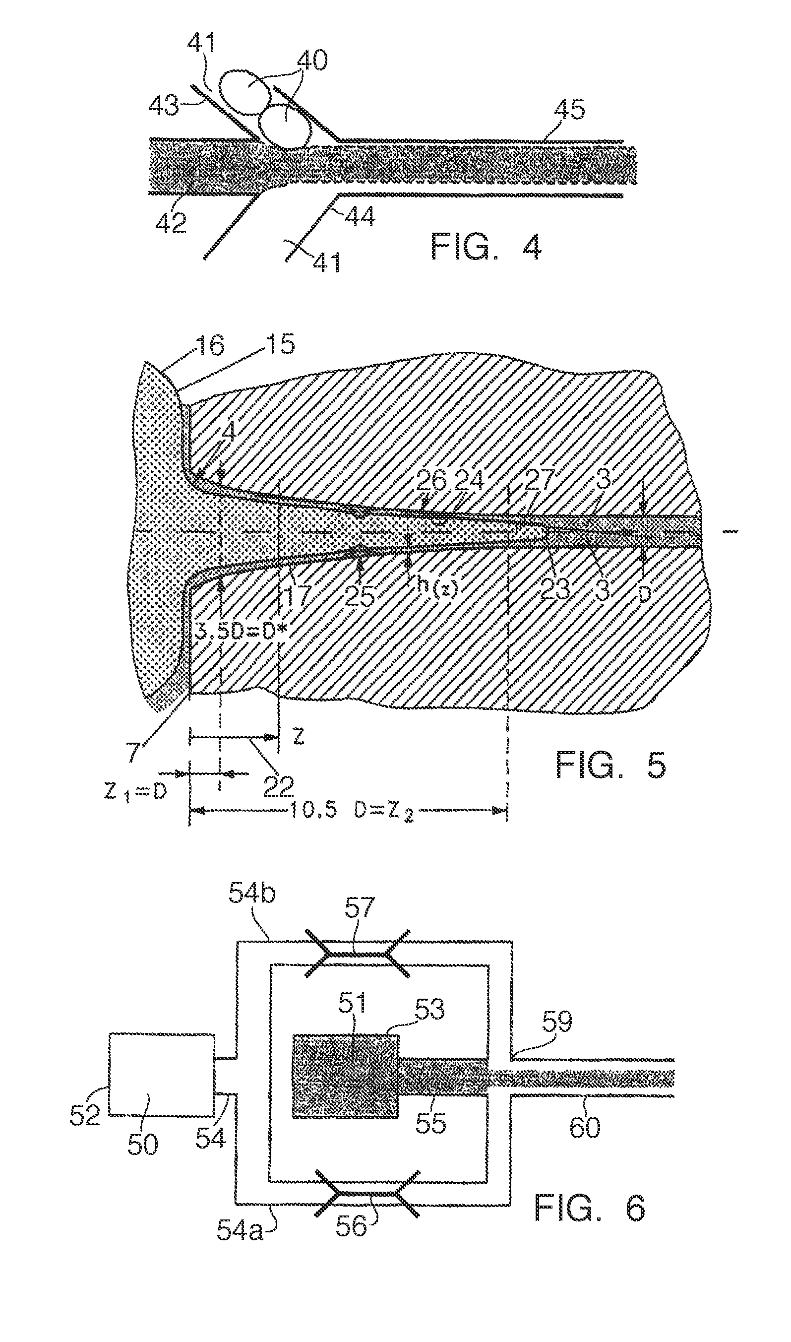
[0028]The first channel 100 is split at the point 102 into the branches 100a and 100b merging with the second channel 101 at a merging point 103 from the left and the right sides, respectively. The pressure drops by a factor DP=P102-P103, where P102 is the pressure in channel 100 just before the point of branching point 102, and P103 is the pressure in channel 101 just after the merging 103.

[0029]In the preferred embodiment of the invention, each of the two channels 100a, 100b has...


PUM


Abstract

A device for mixing at least one first fluid and one second fluid in a micro-flow system, comprising at least two flow restrictors, a first transfer conduit in fluid communication the first og said fluids and a recipient, at least one second transfer conduit in fluid communication with the second of said fluids, the second transfer conduit having at least two fluid outlets in fluid communication with said first transfer conduit, where each of said outlets of said second transfer conduit is downstream and in fluid communication with the outlet of one of said flow restrictors, and wherein the flow restrictors are bubble-tolerant, being formed to prevent fragmentation of bubbles entering the flow restrictor, into a bubble train consuming the pressure difference between the source and the recipient. Pumping means may be attached to the flow system, possibly being constant-pressure pumps of the kind, where elastomer bladders squeeze a fluid into the channels.

Description

CROSS REFERENCE TO RELATED APPLICATIONS[0001]This application is entitled to the benefit of and incorporates by reference essential subject matter disclosed in International Patent Application No. PCT / DK2005 / 000775 filed on Dec. 8, 2005 and Danish Patent Application No. PA 2004 01901 filed Dec. 8, 2004.FIELD OF THE INVENTION[0002]The present invention relates to mixing of fluids in a micro-flow system, without any risk of bubbles clogging the flow paths and thereby destroying the reliability of the mixing. The mixer comprises transfer conduits like capillary tubes or channels engraved on the surface of a plate. The fluids are merged in a laminated manner. Flow restrictors are inserted into the transfer conduits to ensure stable flow rates, but also possess the ability to segment gas bubbles passing the flow restrictors into sizes unable to clog the flow paths.BACKGROUND OF THE INVENTION[0003]Systems with flows in the order of micro-litres per minute are often realized by connecting ...

Claims


Application Information

Patent Timeline
IPC IPC(8): G05D7/01G05D11/02B01F3/08F15D1/00
CPCB01F13/0093B01F13/0062Y10T137/87652Y10T137/87346Y10T137/87676B01F33/3011B01F33/3039
Inventor DIRAC, HOLGER
Owner CEQUR SA
Why Eureka
Try Eureka