Apparatus and Method for Interpolating the Intensities of Scanned Pixels from Source Pixels

a technology of interpolation and source pixels, applied in the field of electronic image generators, can solve the problems of increasing the cost, complexity, and power consumption of the system, and increasing the complexity, size and cost of image generators b>12, so as to reduce the error in beam position and reduce the number of harmonics

Inactive Publication Date: 2009-08-27
MICROVISION
View PDF29 Cites 5 Cited by
  • Summary
  • Abstract
  • Description
  • Claims
  • Application Information

AI Technical Summary

Benefits of technology

[0017]For example, sweeping the beam non-linearly in the vertical dimension can also reduce the

Problems solved by technology

Unfortunately, uni-directionally sweeping the beam 18 in the vertical (Y) dimension may increase the cost, complexity, size, and power consumption of the system 10.
Unfortunately, such a feedback loop often includes complex circuitry that can occupy significant layout area, and, thus

Method used


Image

  • Apparatus and Method for Interpolating the Intensities of Scanned Pixels from Source Pixels
  • Apparatus and Method for Interpolating the Intensities of Scanned Pixels from Source Pixels
  • Apparatus and Method for Interpolating the Intensities of Scanned Pixels from Source Pixels

Examples


Embodiment Construction

Bi-Sinusoidal Scanning Pattern

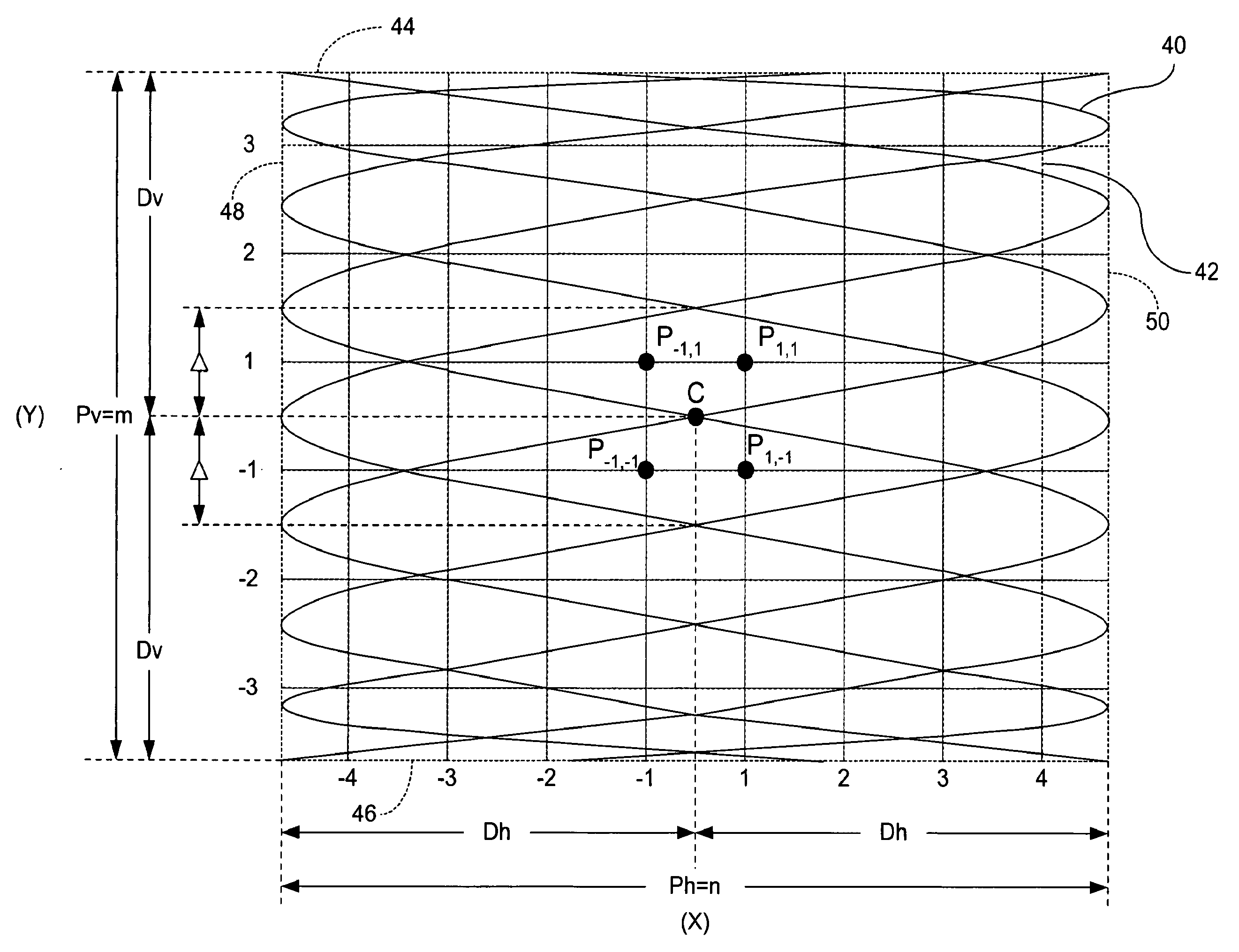
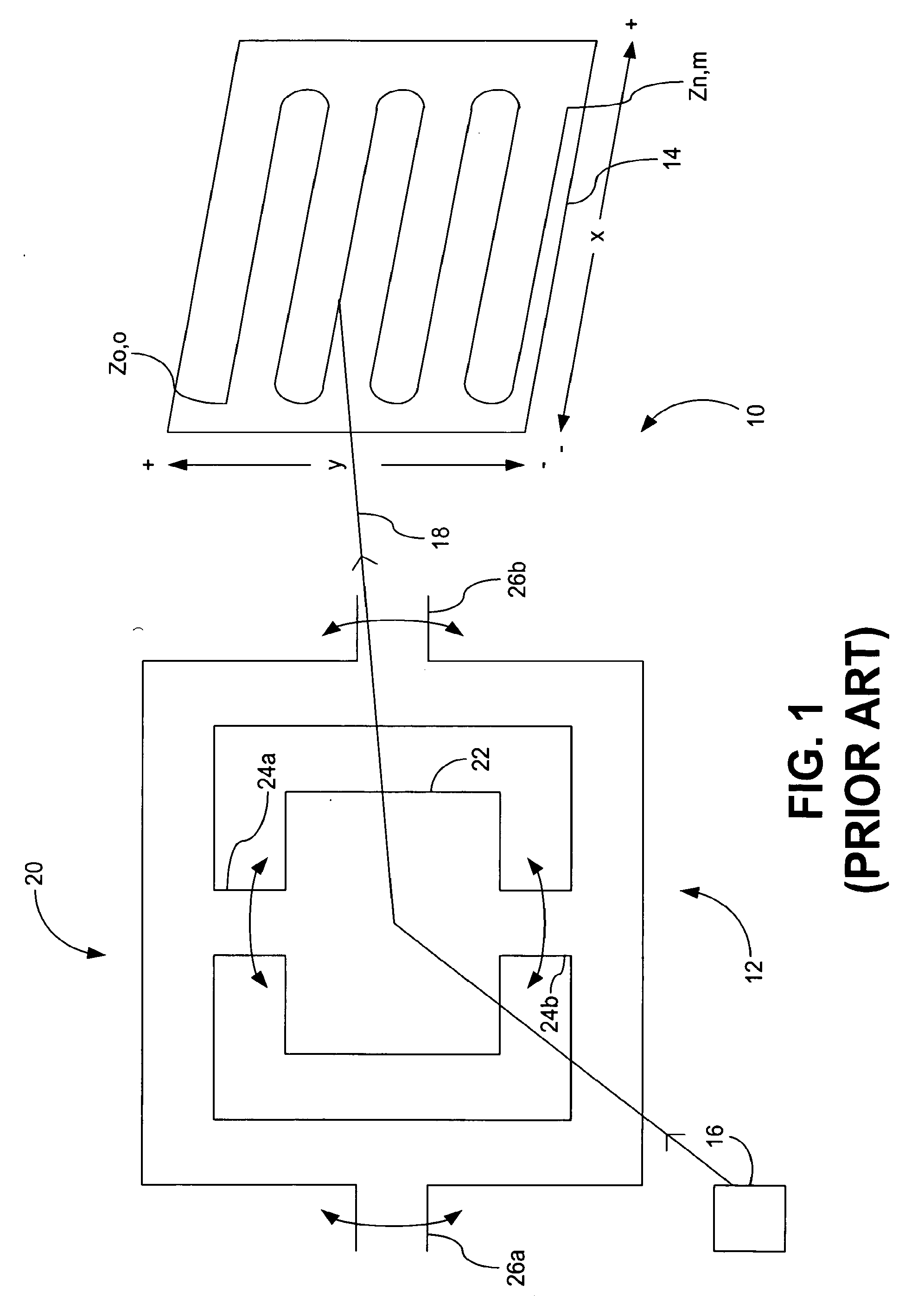
[0036]Referring to FIGS. 4-8, one general embodiment according to the invention is a scan assembly, similar to the scan assembly 20 (FIG. 11), that bi-directionally sweeps the image beam in the vertical (Y) dimension. That is, the image beam is “on” while the scan assembly sweeps the beam from the top to the bottom of the screen, and is also “on” while the scan assembly sweeps the beam from the bottom back to the top of the screen.

[0037]Still referring to FIGS. 4-8, in one embodiment the scan assembly sweeps an image beam sinusoidally and bi-directionally in both the horizontal (X) and vertical (Y) dimensions, although one can use a sweeping function other than a sinusoid in either of the horizontal and vertical dimensions as discussed below in conjunction with FIG. 12. For clarity, “bi-sinusoidal” is used to denote a sinusoidal and bi-directional sweep of the image beam in both the horizontal (X) and vertical (Y) dimensions. Because both of the horizon...


PUM


Abstract

A scan assembly of an image generator sweeps an image beam in a first dimension at a first rate and bi-directionally in a second dimension at a slower rate. Sweeping the beam bi-directionally in the vertical dimension (generally the dimension of the lower sweep rate) can reduce the scanning power by eliminating the flyback period, and, where the scan assembly includes a mechanical reflector, can reduce the error in the beam position without a feedback loop by reducing the number of harmonics in the vertical sweep function. Furthermore, because the image beam is “on” longer due to the elimination of the flyback period, the scanned image is often brighter for a given beam intensity. The scan assembly may also sweep the image beam non-linearly in the vertical dimension, and this sweep may be bi-directional or uni-directional. Sweeping the beam non-linearly can also reduce the error in the beam position by reducing the number of harmonics in the vertical sweep function.

Description

CLAIM OF PRIORITY[0001]This application claims priority to U.S. Provisional Application Ser. No. 60 / 381,569, filed on May 17, 2002, which is incorporated by reference.BACKGROUND[0002]An electronic image generator, such as television set, scans a viewable image, or a sequence of viewable video images, onto a display screen by electronically sweeping an electromagnetic image beam across the screen. For example, in a television set, the image beam is a beam of electrons, and a coil generates a linearly increasing magnetic field or electric field to sweep the beam.[0003]An optical image generator is similar except that it scans a viewable image onto a display screen by mechanically sweeping an electromagnetic image beam across the screen. Or, in the case of a Virtual Retinal Display (VRD), the optical image generator scans a viewable directly onto a viewer's retina(s).[0004]FIG. 1 is a view of a conventional optical image-display system 10, which includes an optical image generator 12 a...

Claims


Application Information

Patent Timeline
IPC IPC(8): G09G3/00G02B26/10G01S17/42G02B7/182G02B26/08G02B27/02G06K7/00G09G3/02H04N1/113H04N3/08H04N5/12
CPCG02B26/0816H04N3/08G09G3/02
Inventor BROWN, MARGARETFREEMAN, MARKLEWIS, JOHN R.BOVEE, JIMSPRAGUE, RANDY
Owner MICROVISION
Why Eureka
Try Eureka