

Machining unit and machine tool
a technology of machining unit and machine tool, which is applied in the direction of turning machine accessories, manufacturing tools, mechanical equipment, etc., can solve the problems of increasing costs, difficult to maintain machining accuracy, and high cost, and achieve the effect of good cutting capability of the tool
- Summary
- Abstract
- Description
- Claims
- Application Information
AI Technical Summary
Benefits of technology
Problems solved by technology
Method used
Image

Examples
first embodiment
Machine Tool 1
[0063]FIG. 3 is a perspective view of a machine tool 1 including a machining unit 11 according to the first embodiment. In the following description, of three directions of XYZ axes, which are perpendicular to each other, X-axis direction is also referred to as a right-to-left direction, Y-axis direction is also referred to as a vertical direction, and Z-axis direction is also referred to as a fore-and-aft direction, as shown in FIG. 3.
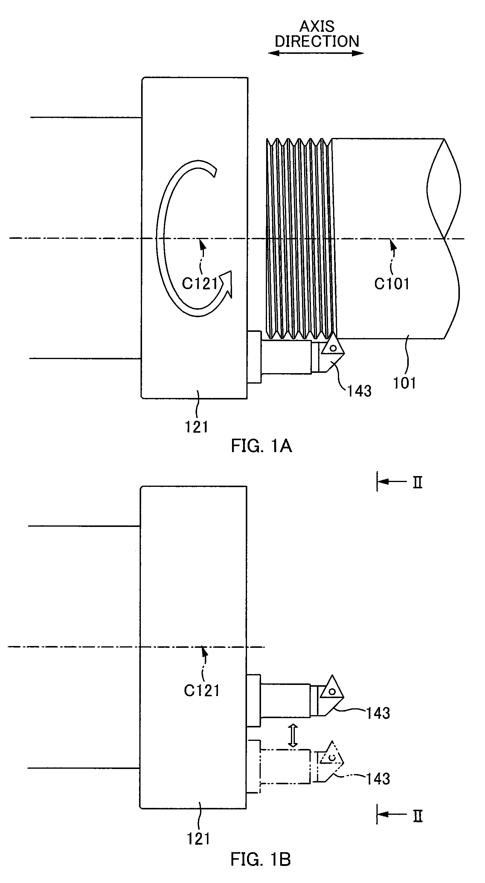
[0064]When a cylindrical pipe 101, for example, is a workpiece to be processed, this machine tool 1 is for screw-threading to an outer circumferential surface or an inner circumferential surface of the pipe. Therefore, the machine tool 1 includes: a stand 3 on which the pipe 101 is placed and that holds the pipe 101 immovably; a head housing 15 that is supported by a column 5 and can move straight in Y direction, the column 5 being capable of moving straight in each of X and Z directions independently; and the machining unit 11 that is s...
second embodiment
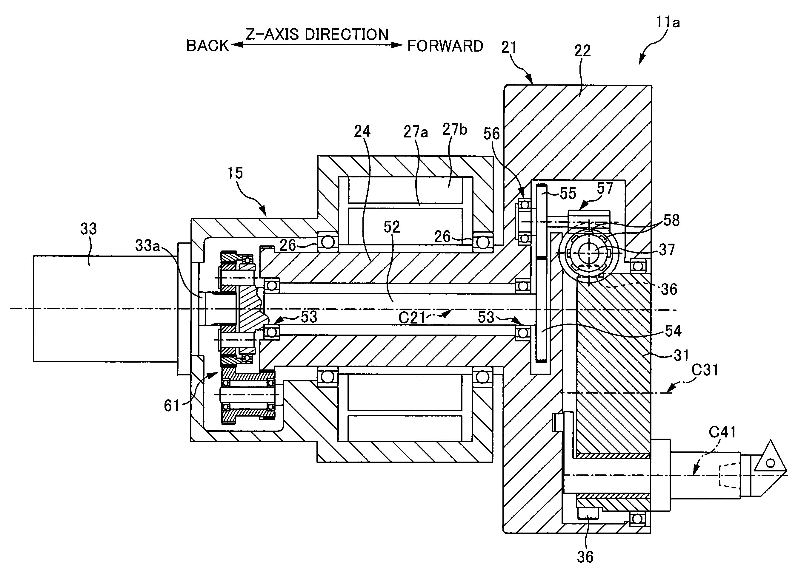
Machining Unit 11a
[0086]FIGS. 8 to 9C are diagrams for illustrating a machining unit 11a according to the second embodiment. FIG. 8 is a longitudinal cut-away view of the machining unit 11a cut along the rotational axis C21 of the main spindle section 21. FIG. 9A is an enlarged cross-sectional view of a differential gear mechanism 61 for rotating the eccentric rotational section 31. FIG. 9B is a schematic sectional diagram showing a meshing relationship between a sun gear 62, planetary gears 63, and an outer gear 65, taken along line B-B of FIG. 9A. FIG. 9C is a schematic sectional diagram showing a meshing relationship between outer teeth 24a of the main spindle section 21 and teeth 68a of a gear 68, taken along line C-C of FIG. 9A. Note that, for the convenience of understanding the figures, some sections in the cut-away view are not hatched.
[0087]In the above-mentioned first embodiment, a configuration in which the servo motor 33 for driving and rotating the eccentric rotational...
PUM
| Property | Measurement | Unit |
|---|---|---|
| Radius | aaaaa | aaaaa |
Abstract
Description
Claims
Application Information