
Engine lubrication system

a technology of lubrication system and engine, which is applied in the direction of crankshaft, machine/engine, mechanical apparatus, etc., can solve the problems of increasing the pressure difference between the crank chambers, affecting the operation of the crank chamber, and reducing the center of gravity of the engine, so as to achieve sufficient oil collection capacity and reduce the weight and installation space. , the effect of reducing the cost and weigh

Active Publication Date: 2009-09-03
TOYOTA JIDOSHA KK +1
View PDF15 Cites 16 Cited by
  • Summary
  • Abstract
  • Description
  • Claims
  • Application Information

AI Technical Summary

Benefits of technology

[0012]The present invention provides a dry-sump lubrication system installed in a multi-cylinder engine of which cost, weight, and installation space can be reduced by using a small number of pumps, and which can still secure a necessary and sufficient oil collection capacity.
[0013]An aspect of the present invention relates to an engine lubrication system. The lubrication system takes out oil from a lower portion of a multi-cylinder engine with pumps, temporarily stores the oil in an oil storage section that is located separately from the engine, and supplies the oil in the oil storage section to a portion to be lubricated of the engine. In this lubrication system, the number of the pumps to be used is at least one and less than the number of crank chambers of the engine partitioned by crankshaft bearing portions. Oil collection passages are respectively provided for the crank chambers. A designated number of the oil collection passages are merged and connected to at least one of suction ports of the pumps. A pressure variation suppression section is provided between the suction port of the pump and the designated number of the crank chambers to be merged. The pressure variation suppression section suppresses pressure variations in the crank chambers.
[0014]The lubrication system in accordance with the aspect of the present invention is assumed to be a dry-sump lubrication system. This lubrication system makes it possible to reduce the stirring resistance of the oil in the crank chambers, and to lower the center of gravity of the engine.

Problems solved by technology

This related art is disadvantageous in lowering the center of gravity of the engine since the oil collection chamber is located under the crank chambers of the engine.
This increases the pressure difference between the crank chambers.
Therefore, it is concerned that the oil in the oil collection chamber may flow back into crank chambers at a negative pressure, and that the scavenge pump may not be able to smoothly collect the oil.
Although the lubrication systems in accordance with the above related arts use a single scavenge pump and are therefore advantageous in terms of cost, weight, and installation space, the oil collection efficiency may be low as discussed above.
Japanese Patent No. 3052002 discloses that the lubrication system is also applicable to multi-cylinder engines, but does not at all disclose how the lubrication system can be applied to the multi-cylinder engines.

Method used


Image

  • Engine lubrication system
  • Engine lubrication system
  • Engine lubrication system

Examples


first embodiment

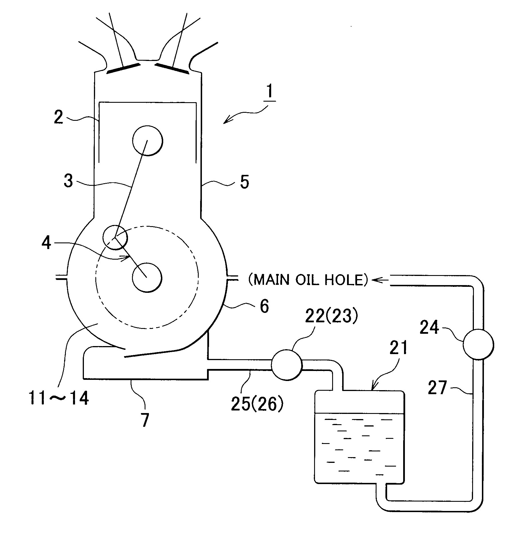
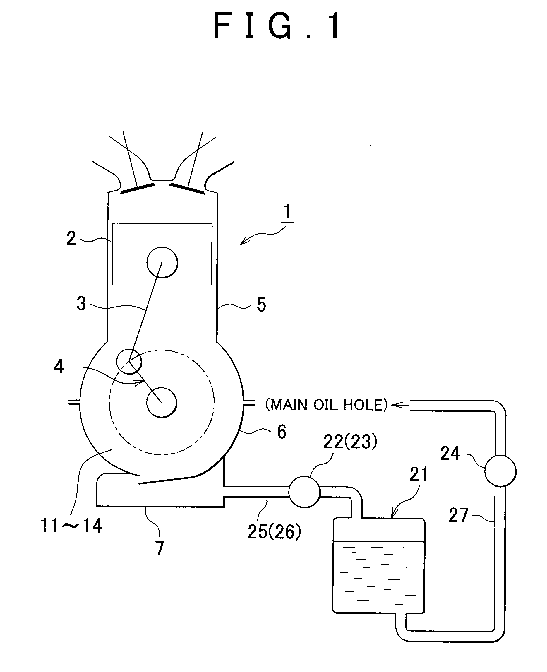
[0049]FIGS. 1 to 4 show a first embodiment of the present invention. First, the dry-sump system will be briefly described with reference to FIG. 1.

[0050]FIG. 1 shows an inline 4-cylinder engine 1 as viewed from the front side of the vehicle. As shown in the drawing, the engine 1 is provided with cylinders (no reference numeral given) arranged in line (in the direction perpendicular to the sheet surface of FIG. 1), and pistons 2 are housed in the respective cylinders so as to be vertically reciprocable.

[0051]Reciprocal motion of the pistons 2 is converted into rotational motion of a crankshaft 4 via connecting rods 3. Oil is supplied to sliding portions of the pistons 2 and the cylinders and bearing portions of the connecting rods 3 and the crankshaft 4, in order to reduce friction at sliding and rolling portions and perform temperature adjustment (cooling or heating) in various portions of the engine 1.

[0052]The engine 1 is equipped with a dry-sump lubrication system. The dry-sump l...

second embodiment

[0096]FIGS. 5 to 7 show a second embodiment of the present invention. The second embodiment is different from the above first embodiment in that a single scavenge pump 22 is used. Other structure and operations are basically the same as those of the first embodiment discussed above. Thus, only the differences from the above first embodiment will be described in detail here.

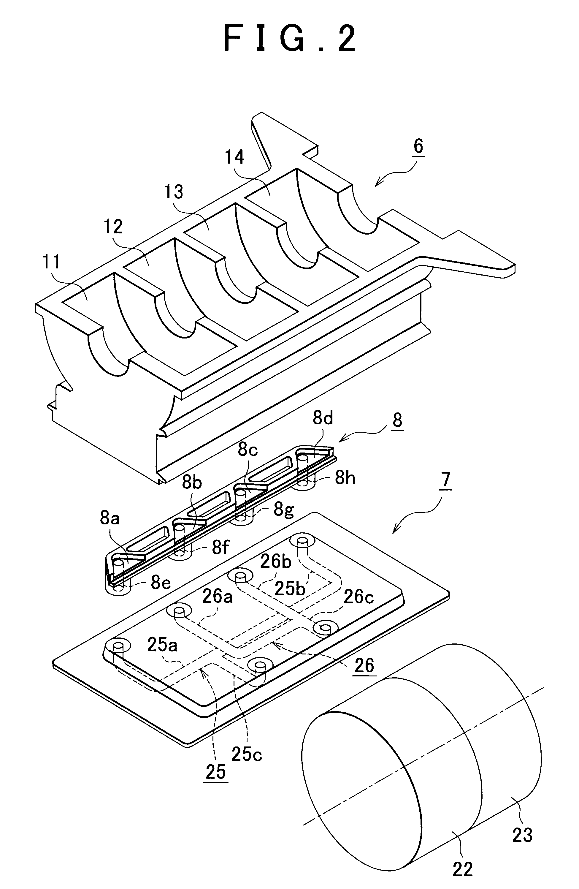
[0097]Specifically, in order to allow the single scavenge pump 22 to collect oil in the four partitioned crank chambers 11 to 14, an oil collection passage 28 with a 4-in-2-in-1 construction is used.

[0098]The oil collection passage 28 has such structure as obtained by further merging the respective downstream merged portions 25c, 26c of the two oil collection passages 25, 26 shown in the above first embodiment.

[0099]That is, the oil collection passage 28 has four upstream branched portions 28a to 28d, two intermediate merged portions 28e, 28f, and one downstream merged portion 28g.

[0100]The four upstream branched...

third embodiment

[0103]FIGS. 8 and 9 show a third embodiment of the present invention. The third embodiment is different from the above first and second embodiments in the structure of the pressure variation suppression section. Other structure and operations are basically the same as those of the above first and second embodiments. Thus, only the differences from the above first and second embodiments will be described in detail here.

[0104]Specifically, as shown in FIGS. 8 and 9, oil collection passages 31, 34 are separately connected to the first crank chamber 11 and the fourth crank chamber 14 in which pistons move up and down in synchronization. The two oil collection passages 31, 34 are connected to a first chamber 35. The first chamber 35 is connected to the first scavenge pump 22 with a common passage 35a of the first chamber 35.

[0105]Meanwhile, as shown in FIGS. 8 and 9, oil collection passages 32, 33 are separately connected to the second crank chamber 12 and the third crank chamber 13 in w...


PUM


Abstract

An engine lubrication system for a multi-cylinder engine, comprising: plurality of crank chambers that are partitioned by crankshaft bearing portions of the engine; pumps that take out oil from a lower portion of the engine; oil collection passages that are respectively provided for the crank chambers, a designated number of the oil collection passages being merged and connected to at least one of suction ports of the pumps; an oil storage section that temporarily stores the oil taken out from the lower portion of the engine; a lubrication part that supplies the oil in the oil storage section to a portion to be lubricated of the engine; and a pressure variation suppression section that is provided between the suction ports of the pumps and the designated number of the crank chambers to be merged, the pressure variation suppression section suppressing pressure variations in the crank chambers.

Description

INCORPORATION BY REFERENCE[0001]The disclosure of Japanese Patent Application No. 2008-049716 filed on Feb. 29, 2008, including the specification, drawings and abstract is incorporated herein by reference in its entirety.BACKGROUND OF THE INVENTION[0002]1. Field of Invention[0003]The present invention relates to a lubrication system installed in a multi-cylinder engine (internal combustion engine) for vehicles such as automobiles, for example. In particular, the present invention provides a so-called dry-sump lubrication system.[0004]2. Description of Related Art[0005]In general, a dry-sump lubrication system takes out oil and blow-by gas from the lower portion of the engine with a scavenge pump and temporarily stores the oil in an oil tank located separately from the crank chamber. The lubrication system supplies the oil in the oil tank with a feed pump to portions of the engine to be lubricated, where lubrication or temperature adjustment (cooling or heating) is required. Thus, fr...

Claims


Application Information

Patent Timeline
Patent Type & Authority Applications(United States)
IPC IPC(8): F01M1/02
CPCF01M1/04F01M2001/126F01M1/12F01M13/00F01M13/04
Inventor KAWAMURA, HIROSHIMAMIYA, SHUNJINOWATARI, NOBORUUEMA, HITOSHI
Owner TOYOTA JIDOSHA KK
Learn More